ENiQ® Wall Readers & Terminals
_____________________________________________________________________________________
25
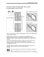
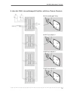
Fig. 12: Wiring diagram for ENiQ AccessManager® and three ENiQ
®
Passive Readers
(HiSec) via RS485
Configuration ENiQ AccessManager® HiSec & ENiQ
AccessManager® Terminal HiSec
Standard configuration
Occupation of the controller inputs/outputs:
Input 1 = Door contact (opener)
Input 2 = External door opening contact
(release button/closer)
Output =
Potential-free relay-changeover contact
(e.g. for triggering the
actuator)
Description
The upper LED is lit red permanently in the idling state. If an authorised locking
medium is presented, the upper red LED goes off and the lower green LED and the
buzzer (acoustic signal) are actuated.
If data are read from the locking medium or written onto the locking medium,
the upper red LED goes off and the lower LED flashes lilac during the
reading/writing process. Once the reading/writing process has been
completed, the lower LED lights up green for as long as contact is m aintained.
Then the lower LED goes off and the upper LED lights up red permanently
again.
The output is triggered for the set contact exposure time (refer also to page 23).
This is set to 5 seconds in the condition on delivery. During this time the lower
LED is lit green permanently.
The output and the permanently lit state of the lower green LED are switched off
when the contact exposure time expires. Then the upper LED is lit red permanently
again.
When the external door opening contact is pressed, signalling and triggering of
the output take place to the same extent as if an authorised locking medium
has been presented.
The locking medium can be read on both units. Release is signalled on both units
when an authorised locking medium is used. An unauthorised locking medium is
signalled where it is presented.


