


ENiQ® Wall Readers & Terminals
_____________________________________________________________________________________
20
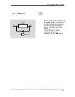
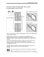
Connection ENiQ AccessManager® Compact, ENiQ
AccessManager® Terminal Compact & ENiQ AccessManager®
ITT
Caution! Ensure a suitable voltage supply and note the positions of the
DIP switches.
Fig. 9: Wiring diagram
Actuators (door openers, etc.) are controlled by the DOM device by means of a
potential-free relay changeover contact. One potential-free opener contact (C-Ö)
and one potential-free closer contact
(C-S) are available.
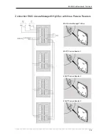
You can connect potential-free switches or buttons to the inputs. These inputs must
be occupied according to the stored configuration. The standard configuration is
factory-set. Input IN1 is the door contact (opener) and input IN2 the release button
(closer).
Please note! Note the maximum cable resistance and the maximum
cable length specified on the technical data sheet.
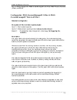
Caution! For design reasons we have had to change the connections of the
ENiQ AccessManager® /Terminal/ITT and Passive Reader compared to
the ELS
®
AccessManager /Terminal and Passive Reader. Before you
continue with installation, check all the connections again. If the wiring is
not done correctly, system components can become damaged.