ENiQ® Wall Readers & Terminals
_____________________________________________________________________________________
8
Proceed according to the sequence described and observe the notes and
figures.
Caution! When installing the system, always comply with the
regulations of the German Association for Electrical, Electronic &
Information Technologies (VDE) and your local power supply
company.
Caution! Material damage can be caused by the excessive
tightening of screw fittings. Always observe the specified
tightening torques.
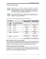
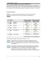
Caution! If you wish to operate the ENiQ AccessManager® or ENiQ
AccessManager® Terminal with an ENiQ
®
Passive Reader via the
RS485 interface, DIP switches 1 and 2 on the controller and on the
ENiQ
®
Passive Reader must be switched ON (see page 13). Where
more than one ENiQ
®
Passive Reader is used, note and follow the DIP
switch settings on pages 14 and 15.
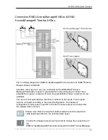
Caution! With an ENiQ
®
Module Reader DIP switches 1 and 2 of the
ENiQ AccessManager® or ENiQ AccessManager® Terminal
controller, connected to an external reader via the RS485 interface,
must be set to ON. The ENiQ
®
Module Reader is configured this way
in the factory.
Please note! As a voltage supply for the ENiQ AccessManager®,
ENiQ AccessManager® Terminal or ENiQ AccessManager® ITT you
require a stabilised, sufficiently dimensioned
12 V to 24 V AC/DC power supply which is not included in the
scope of delivery. Alternatively, you can set up the voltage supply
via Power over Ethernet (PoE) (applies for the controller of HiSec
variants only).
Please note! If you wish to connect the controller of an ENiQ
AccessManager® HiSec, ENiQ AccessManager® Terminal HiSec or
ENiQ
®
Module Reader to the network via PoE (Power over Ethernet),
an external power source is always required for the Passive Reader(s)
or the external reader of the ENiQ
®
Module Reader.
Please note! As a voltage supply for the ENiQ
®
Module Reader you
require a stabilised, sufficiently dimensioned 12 V to 24 V DC power
supply which is not included in the scope of supply.
The connection between the controller and a Passive Reader or
external reader by PoE is
not
possible. The connection must be set up
as RS 485. (See page 22 onwards)

