background image

35

BH 5910 / 200217 / 190A

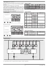
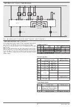
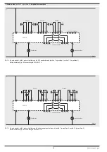
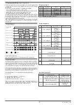
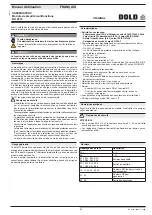
  2-Hand control and E-stop

 (switch 1 in position 6)

2 pairs of 2-hand buttons can be connected in this function together with 
1 e-stop loop. The number of connected button pairs has to be selected 
on the device.
K1 and K2 can only be activated, if 4 conditions are fulfilled:
-  First all button pairs have to be in initial position.
-  The e-stop contacts must be closed and manual start must be activated.
-  Both buttons of 1 pair have to be pressed within 0.5 sec.
-  All connected pairs have to be operated within 15 sec.
If  changeover contacts are used in the 2-hand buttons the switchover time 
has to be less then 50 ms. If it is longer the outputs K1 and K2 are switched 
off and the unit gives failure code 7. This failure  is stored and can only be 
reset by disconnecting the auxiliary supply.
After e-stop or power failure the start button must always be activated. 
The e-stop loop must be closed and all 2-hand button pairs must be in 
initial position.

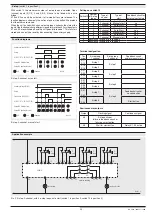
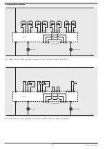
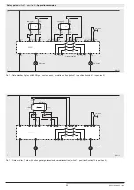
2-hand control and e-stop,
with 2 pairs of buttons with 2 NO contacts each and 1 e-stop loop


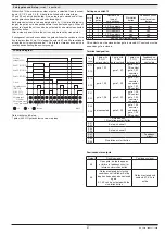
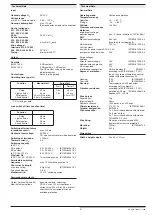
Function diagram

Button 2 S2 (S23/S24)

Auxiliary voltage
(A1/A2)

Button 1 S1 (S11/S12)

Button 1 S2 (S13/S14)

Button 2 S1 (S21/S22)

E-stop

Start button (S43/S44)

K1/K2
(13-14, 23-24, 33-34)

48 (no button activated)

58 (all buttons activated)

: off

: on

: flashing

M8447


Set-up instructions

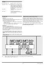
The device has to be connected as shown in the application examples. When 
connecting the push-buttons in parallel or in series the safe function of the 
relay is disabled. The buttons must be designed and installed in a way, that 
it is not possible to manipulate or to operate them without intention.

The distance between push buttons and dangerous area must be chosen 
in a way that it is not possible to reach the dangerous area after release of 
one button before the dangerous movement comes to standstill.

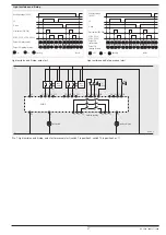
The safety distance "S" is calculated with the following formula:
S = V x T + C

a)  moving speed of person V = 1 600 mm/s
b)  stopping time of the machine T (s)
c)  Additional safety distance C = 250 mm

If the risc of accessing the dangerous area is prohibited while the push 
buttons are pressed e.g. by covering the buttons, C can be 0. The minimum 
distance has to be in this case 100 mm. See also EN 574.

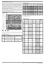
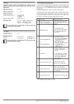
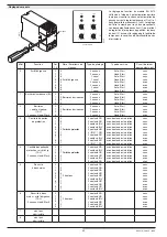
Settings on switch 10

Switch 

10

Number of

button pairs

Type of 

button contacts

Feedback circuit for 

external contactors

0

1

2 NO contacts

no

1

2

2 NO contacts

no

2

1

2 C/O contacts

no

3

1

2 NO contacts

yes

4

2

2 NO contacts

yes

5

1

2 C/O contacts

yes

6-9

position not allowed (failure 5)

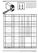
Terminal designation

Ter-

minal

Pair of buttons with

2 NO contacts each

Pair of buttons with

2 C/O contacts each

Feedback circuit for 

external contactors

S11

S12

Pair 1, button S1

button S1,

NO contact

button S1, 

common connector

S14

S13

Pair 1, button S2

button S1,

common connector

button S1, 

NC contact

S21

S22

Pair 2, button S1

button S2,

NC contact

button S2, 

common connector

S24

S23

Pair 2, button S2

button S2,

common connector

button S2, 

NO contact

1 E-stop loop and 1 Start button

S31

S32

E-stop, channel 1

S34

S33


E-stop, channel 2

S41

S42

not connected

Feedback circuit

S44

S43

Start button

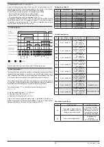
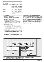
Semiconductor outputs

Output

Flashing signal

Continuous signal

48

E-stop loop open or starting 

conditions not fulfilled or failure 

in feedback circuit or on acknow-

ledge button/start button.

All buttons in initial 

position. For a new start 

all

 buttons have to be

linked according to

the starting conditions.

58

Press acknowledge button.

All buttons are 

activated, 

K1, K2 are energized.

Summary of Contents for SAFEMASTER C BH 5910

Page 1: ...erheitsfunktion mu mindestens einmal im Monat ausgel st werden Das BH 5910 dient dem sicherheitsgerichteten Unterbrechen eines Sicher heitsstromkreises Es kann zum Schutz von Personen und Maschinen in...

Page 2: ...1 2 3 2 2 Lichtschranken 2 2 2 kanalig 2 kanalig 2 kanalig 2 kanalig Auto Start Hand Start Auto Start Hand Start ohne ohne mit mit 3 Schutzt rw chter 0 1 2 3 4 5 6 7 8 9 4 3 2 1 2 Schutzt ren 1 3 1 2...

Page 3: ...kreis Poti 1 Stellung 0 Poti 10 Stellung 4 oder 5 R ckf hrkreis zur berwachung externer Sch tze M ssen die Maschinen Freigabekontakte K1 K2 vervielf ltigt odermu ber zus tzliche leistungsst rkere Sch...

Page 4: ...rgungsspannung A1 A2 Not Aus Starttaste S43 S44 K1 K2 13 14 23 24 33 34 Ausgang 48 Fehlerzustand Ausgang 58 Warten auf Start dunkel hell blinkt M8167_a Not Aus Not Aus Not Aus Not Aus L L M8168_b BH59...

Page 5: ...ti 10 Stellung 1 L L M8169_a BH5910 K1 K2 Maschinen Freigabe 13 23 33 34 24 14 48 58 A2 Warten auf Start A1 Fehlerzustand S11 S12 S14 S13 Not Aus Not Aus Not Aus Not Aus Not Aus Not Aus Not Aus Not Au...

Page 6: ...Starttaste S43 S44 K1 K2 13 14 23 24 33 34 Ausgang 48 Fehlerzustand Ausgang 58 Warten auf Start dunkel hell blinkt M8172_a Sender Sender Sender Sender BWS 1 BWS 2 BWS 3 BWS 4 L L M8173_b BH5910 K1 K2...

Page 7: ...schranken Not Aus Poti 1 Stellung 2 Start Sender Sender BWS 1 BWS 2 L L M8174_b BH5910 K1 K2 Maschinen Freigabe 13 23 33 34 24 14 48 58 A2 Warten auf Start A1 Fehlerzustand S11 S12 S14 S13 S21 S22 S24...

Page 8: ...S43 S44 K1 K2 13 14 23 24 33 34 Ausgang 48 Fehlerzustand Ausgang 58 Warten auf Start dunkel hell blinkt M8175_a Versorgungsspannung A1 A2 BWS Not Aus Starttaste S43 S44 K1 K2 13 14 23 24 33 34 Ausgang...

Page 9: ...3 S14 Simulationstaste S43 S44 T r 1 S3 S21 S22 K1 K2 13 14 23 24 33 34 48 T ren auf bzw Fehler 58 alle T ren zu dunkel hell blinkt M8178_a 3s Einstellungen an Poti 10 Poti 10 Anzahl der Schutz t ren...

Page 10: ...hutzgitter 3 Schiebeschutzgitter 4 S1 S1 S1 S1 S2 S2 S2 S2 L L M8179_a BH5910 K1 K2 Maschinen Freigabe 13 23 33 34 24 14 48 58 A2 T r geschlossen A1 Fehlerzustand geschlossen geschlossen geschlossen g...

Page 11: ...Stellung 3 Poti 10 Stellung 5 Schiebeschutzgitter 1 Schiebeschutzgitter 2 S1 S1 S2 S2 S3 S3 L L M8181_a BH5910 K1 K2 Maschinen Freigabe 13 23 33 34 24 14 48 58 A2 T r geschlossen A1 Fehlerzustand gesc...

Page 12: ...lossen sein F r die Positionsschalterart ffner gilt Bei geschlossener Schutzt r m ssen die Kontakte des Positionsschalters ge ffnet sein Not Aus Versorgungs spannung A1 A2 T r S1 S11 S12 T r S2 S13 S1...

Page 13: ...ulation bzw Start geschlossen offen S11 S12 S14 S13 S21 S22 S24 S23 S31 S32 S34 S33 S41 S42 S44 S43 Not Aus Bild 13 Schutzt rw chter Not Aus Schutzt r berwachungen mit bis zu 20 magnetisch codierten S...

Page 14: ...ht werden kann nachdem die gefahrbringende Bewegung zum Stillstand gekommen ist Der Sicherheitsabstand S wird nach folgender Formel berechnet S V x T C wobei a Greifgeschwindigkeit V 1 600 mm s b Nach...

Page 15: ...llung 5 Poti 10 Stellung 5 Sicherheitsschaltungen Typ III C nach DIN EN 574 L L M8186_a BH5910 K1 K2 Maschinen Freigabe 13 23 33 34 24 14 48 58 A2 Maschine freigegeben A1 Zweihand Zustand ZWEIHAND 1 Z...

Page 16: ...on der Ger te aufgehoben Die Tasten m ssen so beschaffen und angeordnet sein da sie nicht auf einfache Weise unwirksam gemacht oder unbeabsichtigt bet tigt werden k nnen Der Sicherheitsabstand zwische...

Page 17: ...Schlie ern und 1 Not Aus Taster Poti 1 Stellung 6 Poti 10 Stellung 1 Zweihand Sicherheitsschaltungen Typ III A nach DIN EN 574 L L M8189_a BH5910 K1 K2 Maschinen Freigabe 13 23 33 34 24 14 48 58 A2 M...

Page 18: ...chlussfestigkeit max Schmelzsicherung 6 A gG gL IEC EN 60947 5 1 Sicherungsautomat C 8 A Halbleiterausg nge Ausgang Klemme 48 und 58 Transistorausg nge plus schaltend Ausgangsnennspannung DC 24 V max...

Page 19: ...viert werden No Beschreibung Ma nahmen und Hinweise 0 interner Ger tefehler LEDs sind konstant aus Wenn beide LEDs aus bleiben ist das Ger t defekt und mu zur Reparatur 5 Einstellfehler 1 Die Drehscha...

Page 20: ...DANGER CAUTION Dangerous voltage Electric shock will result in death or serious injury Disconnect all power supplies before servicing equipment Safe operation of the device is only guaranteed when usi...

Page 21: ...no no no no no yes yes yes yes 4 Gate monitor E stop 1 E stop button 2 channel manual start 0 1 2 3 4 5 2 1 1 Gate switches 2 1 1 2 NO contacts 2 C O contacts 3 NO contacts 2 NO contacts 2 C O contac...

Page 22: ...failure the unit has to be reset also with the start button The button has to be pressed not longer then 3 sec to allow the unit to energise If one of the functions light curtain safety gate or 2 hand...

Page 23: ...bling Auxiliary voltage A1 A2 E stop K1 K2 13 14 23 24 33 34 Output 48 failure state Output 58 waiting for start off on flashing M8428 Auxiliary voltage A1 A2 E stop Start button S43 S44 K1 K2 13 14 2...

Page 24: ...itch 10 in position 1 waiting for start failure state L L M8426_a BH5910 K1 K2 13 23 33 34 24 14 48 58 A2 A1 S11 S12 S14 S13 E stop E stop E stop E stop E stop E stop E stop E stop S21 S22 S24 S23 S31...

Page 25: ...r start off on flashing M8431 LC 1 LC 2 LC 3 LC 4 L L M8432_a BH5910 K1 K2 13 23 33 34 24 14 48 58 A2 A1 S11 S12 S14 S13 S21 S22 S24 S23 S31 S32 S34 S33 S41 S42 S44 S43 trans mitter trans mitter trans...

Page 26: ...3 S21 S22 S24 S23 S31 S32 S34 S33 S41 S42 S44 S43 trans mitter trans mitter waiting for start failure state machine enabling Settings on switch 10 Switch 10 No of LCs Type of control Type of start Fee...

Page 27: ...on S43 S44 K1 K2 13 14 23 24 33 34 Output 48 failure state Output 58 waiting for start off on flashing M8434 Auxiliary voltage A1 A2 LC E stop Start button S43 S44 K1 K2 13 14 23 24 33 34 Output 48 fa...

Page 28: ...rnal contactors 0 4 2 NO contacts no no 1 3 2 NO contacts yes no 2 2 2 C O contacts no no 3 1 2 C O contacts yes no 4 2 3 NO contacts yes no 5 1 2 C O contacts 1 NO contact yes no 6 3 2 NO contacts ye...

Page 29: ...ed closed closed open open open open safety gate 1 safety gate 2 safety gate 3 safety gate 4 S1 S1 S1 S1 S2 S2 S2 S2 L L M8438_a BH5910 K1 K2 13 23 33 34 24 14 48 58 A2 A1 S11 S12 S14 S13 S21 S22 S24...

Page 30: ...in position 3 switch 10 in position 5 closed open safety gate 1 closed open safety gate 2 S1 S1 S2 S2 S3 S3 L L M8440_a BH5910 K1 K2 13 23 33 34 24 14 48 58 A2 A1 S11 S12 S14 S13 S21 S22 S24 S23 S31...

Page 31: ...33 34 48 gates open or E stop 58 all gates closed e stop loop closed off on flashing M8442 Settings on switch 10 Switch 10 No of gates Number and type of gate switches Simulation button Feedback circu...

Page 32: ...S21 S22 S24 S23 S31 S32 S34 S33 S41 S42 S44 S43 E stop failure state machine enabling 23 23 13 13 14 14 24 24 actuator actuator actuator actuator actuator actuator sensor 1 sensor 11 sensor 2 sensor...

Page 33: ...rson V 1 600 mm s b stopping time of the machine T s c Additional safety distance C 250 mm If the risc of accessing the dangerous area is prohibited while the push buttons are pressed e g by covering...

Page 34: ...ntacts each switch 1 in position 5 switch 10 in position 5 Safety switches Typ III C according to DIN EN 574 L L M8445_a BH5910 K1 K2 13 23 33 34 24 14 48 58 A2 A1 S1 S1 S1 S11 S12 S14 S13 S21 S22 S24...

Page 35: ...ush buttons and dangerous area must be chosen in a way that it is not possible to reach the dangerous area after release of one button before the dangerous movement comes to standstill The safety dist...

Page 36: ...ttons and 2 NO contacts each switch 1 in position 6 switch 10 in position 1 2 hand safety switsches Type III A according to DIN EN 574 machine enabled 2 hand state 2 hand 1 2 hand 2 L L M8448_a BH5910...

Page 37: ...ing cycles Semiconductor outputs Output terminal 48 and 58 transistor outputs switching Nominal output voltage DC 24 V max 100 mA continuous current max 400 mA for 0 5 s internal short circuit over te...

Page 38: ...value approx 1 15 UN 5 residual ripple 7 Input failure 1 A short circuit has been detected on the inputs of the unit 2 The 2 signals of a 2 channel sensor E stop button light curtain are not identical...

Page 39: ...ner des disfonctionnements S assurer que les circuits de protection sont suffisants sur tous les contacts de sortie en cas de charges capacitives et inductives La fonction de s curit doit tre activ e...

Page 40: ...Start Hand Start sans sans avec avec 3 Contr le de portes de protection 0 1 2 3 4 5 6 7 8 9 4 3 2 1 2 Portesdeprotection 1 3 1 2 1 2 contacts NO 2 contacts NO 2 contacts INV 2 contacts INV 3 contacts...

Page 41: ...r le bouton start En cas de coupure r seau galement il doit toujours tre activ par le bouton start La dur e d actionnement du bouton doit tre inf rieure 3 s pour permettre l activation de l appareil S...

Page 42: ...A1 A2 arr t d urgence sortie 48 tat de d faut sortie 58 attente de d marrage teint allum clignotant L L M6112_a BH5910 K1 K2 13 23 33 34 24 14 48 58 A2 A1 S11 S12 S14 S13 S21 S22 S24 S23 S31 S32 S34 S...

Page 43: ...ition 1 lib ration de la machine attente de d marrage tat de d faut L L M6114_a BH5910 K1 K2 13 23 33 34 24 14 48 58 A2 A1 S11 S12 S14 S13 arr t d urgence arr t d urgence arr t d urgence arr t d urgen...

Page 44: ...ignotant BI bouton start S43 S44 K1 K2 13 14 23 24 33 34 M6117 tension d alimentation A1 A2 sortie 48 tat de d faut sortie 58 attente de d marrage teint allum clignotant BI 1 BI 2 BI 3 BI 4 lib ration...

Page 45: ...ion Barri res lumineuses arr t d urgence potentiom tre 1 en position 2 marche BI 1 BI 2 lib ration de la machine attente de d marrage tat de d faut L L M6119_a BH5910 K1 K2 13 23 33 34 24 14 48 58 A2...

Page 46: ...S44 K1 K2 13 14 23 24 33 34 M6120 tension d alimentation A1 A2 arr t d urgence sortie 48 tat de d faut sortie 58 attente de d marrage teint allum clignotant BI K1 K2 13 14 23 24 33 34 M6123 bouton st...

Page 47: ...outes portes ferm es M6125 3s tension d alimentation A1 A2 teint allum clignotant R glages du potentiom tre 10 Pot 10 Nombre des portes Nombre et nature des interrupteurs Bouton de simulation Circuit...

Page 48: ...e ferm ferm ferm ferm ouvert ouvert ouvert ouvert grille de protection coulissante 1 grille de protection coulissante 2 grille de protection coulissante 3 grille de protection coulissante 4 lib ratio...

Page 49: ...t bouton de simulation potentiom tre 1 en position 3 potentiom tre 10 en position 5 porte ferm e ferm ferm ouvert ouvert grille de protection coulissante 1 grille de protection coulissante 2 lib ratio...

Page 50: ...upteur de position doivent tre ouverts arr t d urgence porte S2 S13 S14 porte S3 S21 S22 K1 K2 13 14 23 24 33 34 48 ou arr t d urgence 58 arr t d urgence d verrouill M6132 porte S1 S11 S12 bouton de s...

Page 51: ...tre 1 en position 4 potentiom tre 10 en position 0 ou 3 simulation ou d marrage porte ferm e arr t d urgence d verrouill ferm ouvert grille de protection coulissante lib ration de la machine tat de d...

Page 52: ...selon la formule suivante S V x T C avec a vitesse d atteinte V 1 600 mm s b temps de ralentissement T s c valeur suppl mentaire C 250 mm Si on veut viter en toute s curit une intrusion dans la zone...

Page 53: ...NO chacun potentiom tre 1 en position 5 potentiom tre 10 en position 5 Exemple de branchement de 3 bimanuelles III C selon EN 574 L L M6136_a BH5910 K1 K2 13 23 33 34 24 14 48 58 A2 A1 S1 S1 S1 S11 S1...

Page 54: ...tion et le montage des boutons doivent tre tels qu ils ne puissent tre ni rendus inop rants d une mani re facile ni actionn s in volontairement La distance de s curit entre les boutons et le point dan...

Page 55: ...on A U potentiom tre 1 en position 6 potentiom tre 10 en position 1 Exemple de branchement de 2 bimanuelles III A selon EN 574 combin es avec 1 ATU marche lib ration de la machine machine lib r e tat...

Page 56: ...euvres Sorties semi conducteurs Sortie bornes 48 et 58 sorties transisors commutation vers Tension assign e de sortie DC 24 V courant continu max 100 mA max 400 mA pour 0 5 s protection interne contre...

Page 57: ...lisation de d faut N Description Rem des et remarques 0 D faut interne les DEL sont teintes en permanence Si les 2 DEL restent teintes le module est d fectueux et doit tre r par 5 D faut de r glage 1...

Page 58: ...3 S44 A1 A2 13 23 A1 48 A1 58 14 24 31 32 DE Beschriftung und Anschl sse EN Labeling and connections FR Marquage et raccordements M10339 4 mm PZ 1 0 8 Nm 7 LB IN M10248 A A 10 mm 1 x 0 5 4 mm2 1 x AWG...

Page 59: ...de Les donn es techniques s curitaires de l installation compl te doivent tre d finies par l utilisateur DE Sicherheitstechnische Kenndaten f r Schutzt r BWS 2 Hand EN Safety related data for safety g...

Page 60: ...t europ enne DE Zulassungen und Kennzeichen EN Approvals and Markings FR Homologations et sigles Canada USA A025518 siehe Varianten see variants voir variantes E DOLD S HNE KG D 78120 Furtwangen e mai...

Reviews: