22
BH 5910 / 200217 / 190A
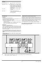
Indication
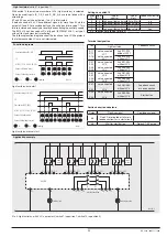
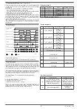
lower green LEDs K1, K2:
On, when relays K1 and K2 are energi-
zed
upper yellow LEDs run 1, run 2: Continuously on on fault free operation.
Regular flashing when waiting for external
action e.g. release of an E-stop button.
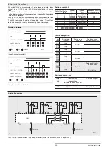
Detected faults are indicated with special
flashing sequences (see flash codes for
fault indication)
Terminal 48:
Flashes, als long as starting condition is
not fulfilled.
Terminal 58:
Flashes while waiting for start or
simulation input (button). Continuous signal
when relay enabled.
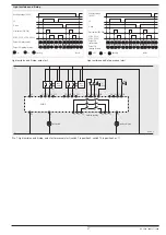
Operating mode
•
Auto start
(with function E-stop and light curtain)
On automatic restart the output contacts are activated when the input
condition for the selected function is fulfilled.
A start-button is only necessary in 2 cases:
- If the function light curtain, safety gate or 2-hand-safety is
combined with E-stop.
- If a function with feedback circuit is selected and the unit has to
be reset after a detected fault without disconnection.
•
Manual start
(with function E-stop and light curtain)
If the unit was deactivated by operating the safety function e.g. by pres-
sing an e-stop button it only can be reset in manual mode by pressing
the start button. After voltage failure the unit has to be reset also with
the start button. The button has to be pressed not longer then 3 sec. to
allow the unit to energise.
If one of the functions light curtain, safety gate or 2-hand-safety is
combined with E-stop the E-stop function always works with manual
restart.
When manual start is selected, the start button is always connected
to terminals S43-S44.
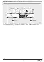
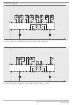
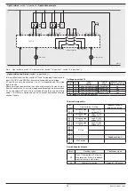
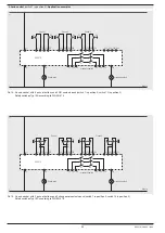
Pic. 1:
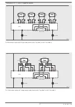
E-stop, 2-channel, with 3 E-stop buttons, manual start and 2 external contactors with feed back circuits
(Switch 1: position 0, switch 10: position 4 or 5)
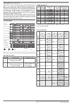
Feedback circuit to monitor external contactors
If the number of contacts has to be increased or a higher current has to be
switched by contactors a feedback circuit with NC contactors can be con-
nected to terminals S41-S42 (see drawing 1). This circuit allows to monitor
the state of the external contactors. The BH 5910 monitors continuously if
the state of this input corresponds to the state of K1 and K2.
In the case of a fault K1 and K2 switch off or do not switch on at all. If the
fault is removed, the BH 5910 has to be reset with the start button.
When operating the unit with feedback circuit the circuit has to be
connected to terminal S41 and S42.
L+
L -
M8424_a
BH5910
K1
K2
13
23
33
34
24
14
48
58
A2-
A1+
start
S11 S12 S14 S13
S21 S22 S24 S23
S31 S32 S34 S33
S41 S42 S44 S43
K21
K22
K22
K21
E-
stop
E-
stop
E-
stop
waiting for start
failure state
machine enabling


