25
BH 5910 / 200217 / 190A
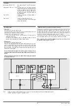
With switch 10 the maximum number of LCs (Light curtains) is selected.
Open (unused) inputs (S_1/S_2 and S_3/S_4) have to be linked with a
wire bridge.
K1 and K2 can only be activated, if no LC is interrupted.
If both channels of an LC have different signals for more then 50 ms the
outputs K1 and K2 are switched off and the unit gives failure code 7. This
failure is stored and can only be reset by disconnecting the auxiliary supply.
The BH 5910 can be used on LCs of type 4 (IEC/EN 61 496-1) or type 2
with self test and crossfault monitoring.
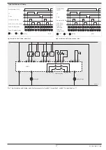
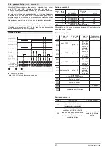
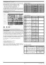
The following function diagrams show the function of one LC. We pretend
that other connected LCs are not interrupted.
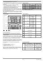
Light curtains
(switch 1 in position 1)
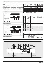
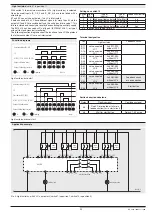
Light curtains, auto start
Light curtains, manual start
Function diagrams
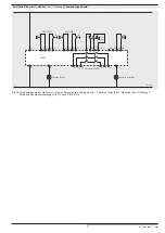
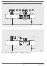
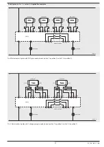
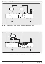
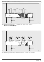
Pic. 5: Light curtains, with 4 LCs, auto start; (switch 1 in position 1, switch 10 in position 0)
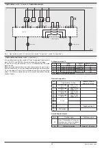
Application example
Auxiliary voltage (A1/A2)
LC
K1/K2 (13-14, 23-24, 33-34)
Output 48 (failure state)
Output 58 (waiting for start)
: off
: on
: flashing
M8430
Auxiliary voltage (A1/A2)
LC
Start button (S43/S44)
K1/K2 (13-14, 23-24, 33-34)
Output 48 (failure state)
Output 58 (waiting for start)
: off
: on
: flashing
M8431
LC 1
LC 2
LC 3
LC 4
L+
L -
M8432_a
BH5910
K1
K2
13
23
33
34
24
14
48
58
A2-
A1+
S11 S12 S14 S13
S21 S22 S24 S23
S31 S32 S34 S33
S41 S42 S44 S43
trans-
mitter
trans-
mitter
trans-
mitter
trans-
mitter
waiting for start
failure state
machine enabling
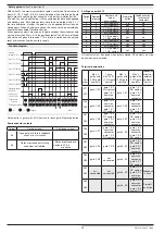
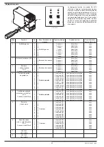
Settings on switch 10
Switch
10
No. of
LCs
Type of
control
Type of
start
Feedback circuit for
external contactors
0
4
2-channel light curtains Auto-Start
no
1
3
2-channel light curtains Manual start
no
2
3
2-channel light curtains Auto-Start
yes
3
3
2-channel light curtains Manual start
yes
4-9
position not allowed (failure 5)
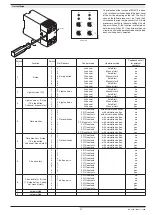
Terminal designation
Ter-
minal
Light curtains
Feedback circuit
and /or manual start
S11
S12
S13
S14
not connected
LC 1
not connected
LC 1
link S11-S12
without LCI 1
link S13-S14
without LC 1
S21
S22
S23
S24
not connected
LC 2
not connected
LC 2
link S21-S22
without LC 2
link S23-S24
without LC 2
S31
S32
S33
S34
not connected
LC 3
not connected
LC 3
link S31-S32
without LC 3
link S33-S34
without LC 3
S41
S42
not connected
LC 4
link S41-S42
without LC 4
Feedback circuit
or no connection
S43
S44
not connected
LC 4
link S43-S44
without LC 4
Start button
Sorties à semi-conducteurs
Output
Flashing signal
Continuous signal
48
One LC interrupted or failure in
feedback circuit or in start circuit
58
Wait for start button
Relay K1, K2 active


