23
HYDRAULIC SYSTEM (Continued....)
BRUSH ADJUSTMENTS
Band Brush
1.
The band brush will wear and lose steel bristles
over time. Check often to be sure the bristles are
removing metal chips from the blade tooth gullets,
but are not touching the bottom of the gullets.
2.
Move the brush closer to the blade as normal wear
occurs. Replace the brushes when necessary.
Band Wper
1.
A wiper located at approximately the ten (10) o'clock
position from the lower bandwheel removes coolant
residue from the moving saw band before it reaches
the upper bandwheel. Adjust or replace the brushes
when necessary.
Carrage Brush
1.
A brush located on the lower front side of the saw
head removes chips and depris from the head
carriage bearing rails as the saw head is traversing.
Adjust or replace the brushes when necessary.
WEAR PLATE REPLACEMENT
1.
The removeable vise jaw and vise bed wear plates
must be replaced before excessive wear causes the
mounting screw heads to become damaged and
makes removal difficult.
Vse Jaw Plates
1.
The machine has two (2) vise jaw wear plates,
one (1) on each jaw. All wear plates are mounted
with low-head screws.
Be sure the vse jaws are
separated and the machne turned off before
tryng to replace the wear plates.
Vse Bed
1.
The inboard and outboard tables has three (3) vise
bed wear plates each. When no rollers are supplied,
there is two (2) each. All wear plates are mounted
with flat head screws.
DOALL hydraulic fluid with an aniline point of
approximately 221° F. (106° C.) will not cause
deteroraton of component seals.
COOLANT SYSTEM
1.
The machine’s coolant drip pan has a 20 gallon
(75.7 liter) capacity.
2.
Check the coolant often for signs of contamination
or breakdown. The drip pan and coolant system
should be drained and cleaned thoroughly when the
cutting fluid becomes undesireable for further use.
If another type of coolant is to be used, the entire
coolant system must be flushed (use DoALL’s Kleen
Flush).
3.
To thoroughly clean the drip pan section below
the saw head, removal of the drip pan may be
necessary.
MACHINE CLEANING
1.
Keep the machine and its parts as clean as possible
to prevent excessive wear and damage.
2.
Use the Flushing Hose as soon as possible to remove
metal chips and other waste materials which may
collect around the saw guides, bandwheels, vises,
slides, etc. The hose has a hand-operated valve
and attaches to the coolant pump.
The DoALL
Company recommends usng the Flushng Hose
to remove chps at least twce per each eght (8)
hour shft, and more often when necessary.
3.
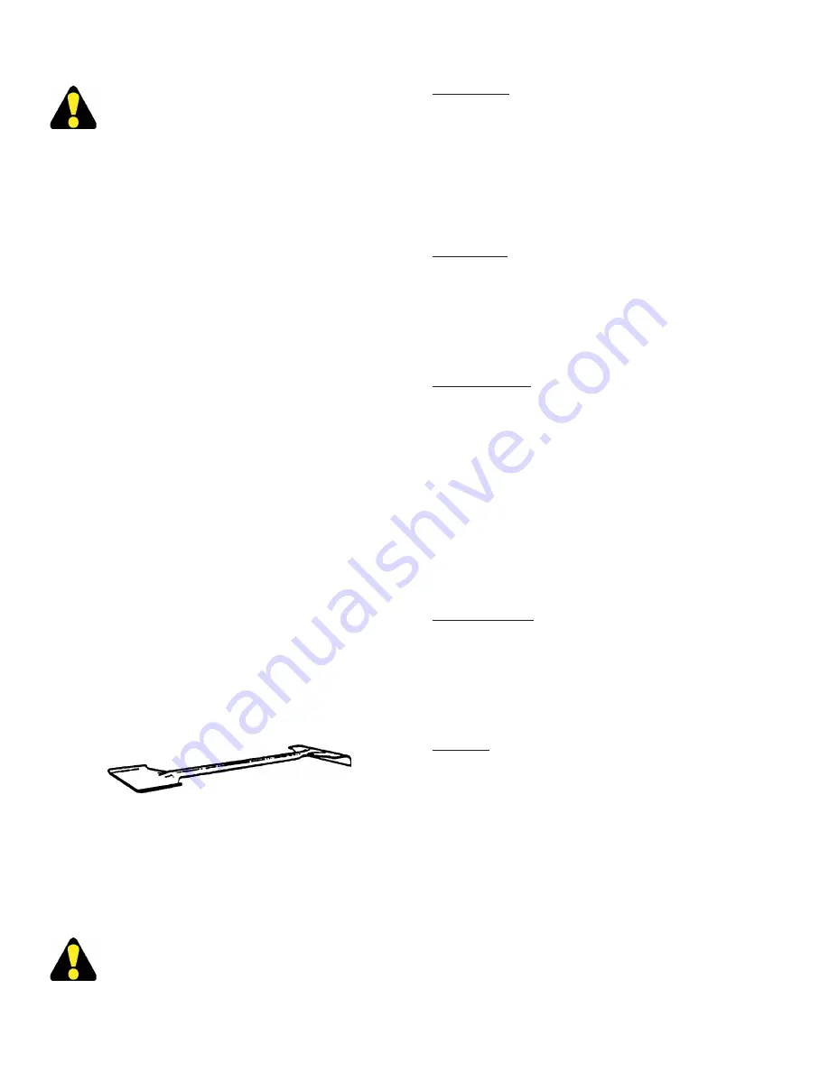
Use the supplied shovel-rake to remove accumulated
metal chips or other waste materials from machine
areas.
Be sure the band drve motor s stopped
before openng machne doors or covers.
Combination Shovel-Rake.
MACHINE ALIGNMENT
1.
Misalignment of the machine’s saw guides, slide
bar, saw band, pivot points, post, etc., will cause
inaccurate sawing.
DO NOT attempt any algnment procedures
not covered by ths manual. Contact a
DoALL servce representatve n such cases
because special fixtures and techniques may
be requred.
Summary of Contents for TF-2025M
Page 1: ...TF 2025M Serial No 543 99101 to Band Sawing Machine Instruction Manual...
Page 5: ...MACHINE DIMENSIONS INCHES 03 MILLIMETERS 1 mm FLOOR PLAN...
Page 6: ...FRONT VIEW MACHINE DIMENSIONS Continued INCHES 03 MILLIMETERS 1 mm...
Page 7: ...MACHINE DIMENSIONS Continued SIDE VIEW INCHES 03 MILLIMETERS 1 mm...
Page 8: ...MACHINE FEATURES SIDE VIEW FRONT VIEW...
Page 9: ...MACHINE FEATURES Continued HEAD ASSEMBLY...
Page 10: ...MACHINE FEATURES Continued PROXIMITY LIMIT SWITCH LOCATIONS REAR VIEW HEAD TOP VIEW...


