background image

20

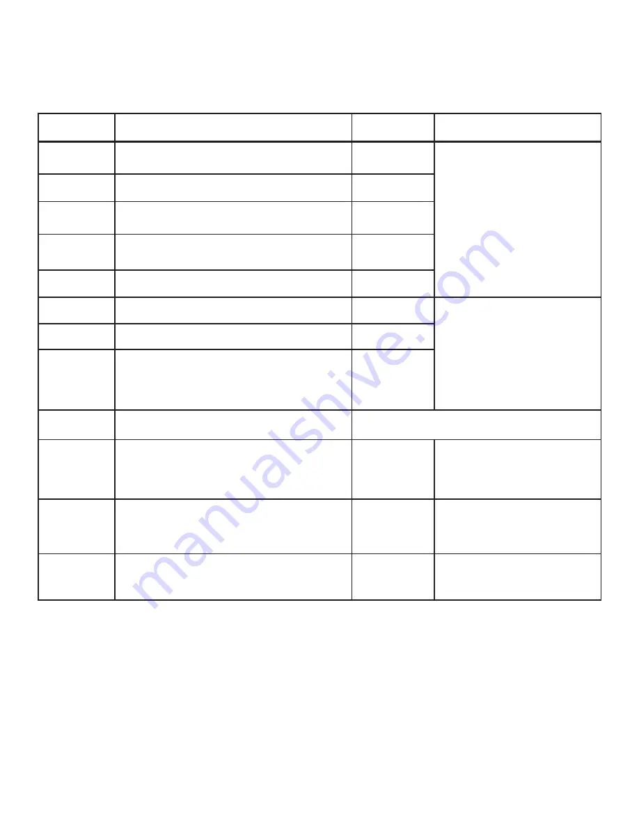
LUBRICATION

LUBRICATION  CHART

LOCATION DESCRIPTION AND

SERVICE RECOMMENDATIONS

RECOMMENDED

LUBRICANT

LUBRICATION

INTERVAL*

LUBRICATION

POINT NO.

1
2

3

MONTHLY

WEEKLY

Insert Adjustment Screws.

   Oil the threads.

INSERT CHANGE

Bandwheel Bearngs.

  One (1) grease fitting each 

bandwheel.

MONTHLY

MONTHLY

Head Carrage Lnear Bearng (Older machnes).

  Four 

(4) grease fittings. 

Current machnes are sealed for lfe.

4

5

Head Pvot Pllow Blocks.

  Two (2) grease fittings.

MONTHLY

6

Post.

  Clean and apply oil.

7

MONTHLY

Mscellaneous:  Vse Sldes, Hnges, Pvot Ponts, 

Component Parts, Unpanted Surfaces, etc.

  To ensure 

function and maintain appearance while reducing wear, 

corrosion, rust, etc.  Apply when and where needed in 

amounts required.

8

AS REQUIRED

High quality, rust and oxidation-inhibited, 

medium hydraulic and general purpose 

industrial oil.

ISO-VG Grade 68 (Formerly ASTM Grade 

No. 315).

Union 76, UNAX RX 68, or equivalent.

Lubricate per manufacturer's recommendations.

9

Electrc/Hydraulc Motors.

   Hydraulic Pump, Coolant, 

Drive and  Optional Chip Conveyor.

10

11

* Lubrcaton ntervals are based on a 8-hour day, 40-hour week.

  Lubrcate more often wth heaver use.

Band Tenson Slde.

   Clean and apply grease.

Vse Movable Jaw Sldes/Gbs.

  Four (4) grease fittings.

1 for each gib. Add two (2) for 

Optonal Outboard Vse

.

Premium quality, multi-purpose lithium-

base, EP (extreme pressure) grease.

NLGI No. 2.

Union 76, UNOBA EP 2, or equivalent.

12

Coolant Reservor (Drp Pan).

 20 gallon (75.7 liter) capacity.  

Chp Conveyor (Optonal).

  50 gallon (189.2 liter) capacity.

Drain, clean and refill whenever coolant becomes 

undesireable for further use.  Clean the mesh strainer at the 

same time.

Premium quality, saw band coolant and 

lubricant.

DoALL cutting fluids and/or oils -  

(Power-Cut).

CHECK DAILY/

AS REQUIRED

CHECK DAILY/

AS REQUIRED

Hydraulc Reservor. 

 20 gallon (75.7 liter) capacity.  

Check oil level daily and keep the reservoir full.  Drain, 

change the filter element and refill after the 1st month;  

every six (6) months thereafter.

Band Mst Lubrcator (Optonal).  

Keep reservoir filled 

and hoses clear.

Contact your DoALL sales representative  

for the best oils and/or fluids for your 

application.

DoALL cutting fluids and/or oils.

CHECK DAILY/

AS REQUIRED

Multi-purpose automatic transmission

fluid.

General Motors Dexron III, or equivalent.

Summary of Contents for TF-2025M

Page 1: ...TF 2025M Serial No 543 99101 to Band Sawing Machine Instruction Manual...

Page 2: ...nine 9 months to file a claim 1 You have fourteen 14 days to report damage not noted at time of delivery a Report damage as soon as possible This makes it easier to prove that it did not happen at co...

Page 3: ...orrespondence or parts orders Specifications contained herein were in effect at the time this manual was approvedforprinting TheDoALLCompany whosepolicyisoneofcontinuous improvement reserves the right...

Page 4: ...0 Laser Line Option 30 Fixed Head Non Tilting 30 3 Head Cant 30 MACHINE DIMENSIONS Floor Plan 1 Front View 2 Side View 3 MACHINE FEATURES Front and Side Views 4 Head Assembly 5 Proximity Limit Switch...

Page 5: ...MACHINE DIMENSIONS INCHES 03 MILLIMETERS 1 mm FLOOR PLAN...

Page 6: ...FRONT VIEW MACHINE DIMENSIONS Continued INCHES 03 MILLIMETERS 1 mm...

Page 7: ...MACHINE DIMENSIONS Continued SIDE VIEW INCHES 03 MILLIMETERS 1 mm...

Page 8: ...MACHINE FEATURES SIDE VIEW FRONT VIEW...

Page 9: ...MACHINE FEATURES Continued HEAD ASSEMBLY...

Page 10: ...MACHINE FEATURES Continued PROXIMITY LIMIT SWITCH LOCATIONS REAR VIEW HEAD TOP VIEW...

Page 11: ...1 If necessary use solvent to remove rust preventive coating applied to exposed bare metal surfaces before shipment LIFTING NEVER lift the machine by its sawing head 1 There is three 3 forged 3 4 10N...

Page 12: ...matic if necessary 8 Place the operating shaft and operating handle of the disconnect switch in the OFF position Then a Close the electrical cabinet door and secure its screws b Now turn the electrica...

Page 13: ...drecommendedbytheLubrication Chart DO NOT let coolant spill over the tray and onto the floor The coolant pump intake must be sufficiently submerged for coolant flow to reach all areas in the coolant s...

Page 14: ...is information is listed according to type of material to be cut and its thickness The Job Selector also has a checklist for proper machine operation and saw band break in procedures JobSelectorrecomm...

Page 15: ...ft Lift Roller Optional This selector switch operates the left hand inboard lift roller in the UP or DOWN positions 2 LeftVise Thisselectorswitchwith OPEN HOLD and CLAMP settings operate the vise on t...

Page 16: ...band speed counterclockwise to decrease it 8 Post This selector switch with DOWN HOLD and UP settings regulate post movement a Rotating the selector to DOWN lowers the post b The UP position raises th...

Page 17: ...radjustingknobuntil thedesiredpressureisshownbytheindicatorgauge Turn the knob clockwise to increase pressure counterclockwise to decrease pressure 15 Chip Conveyor Optional This selector switch with...

Page 18: ...ttings allows the operator to turn the power off or on to the conveyor This is used in conjunction with the Conveyor Speed Direction control 4 Conveyor Speed Direction This two position joystick allow...

Page 19: ...ine to thefollowingconditions a Hydraulicsare ON b Banddrivemotoris OFF c Coolantiscompletely shut off d Saw head is vertical and completely retracted 2 Turn the Band Tension selector switch to OFF Th...

Page 20: ...bandwheel rear flange POST ADJUSTMENT 1 Post and upper saw guide height is regulated by the Post selector switch on the control panel 2 Sawing results will generally be more satisfactory if the post a...

Page 21: ...Using the proper cutting fluid reduces the heat generated during operation It also helps the machine take full advantage of its high speed steel saw bands Literature describing these and other coolant...

Page 22: ...Control selector to FWD AUTO and position the saw band just behind the vise then move the Saw Head Control selector to the HOLD setting 6 Tilt the saw head to desired setting and align for a good cut...

Page 23: ...WD AUTO and then push the Head Rapid Approach pushbutton 2 When pushing the Head Rapid Approach pushbutton the saw head will move forward at a rapid speed until it reaches the feed zone The Feed Force...

Page 24: ...11 Lubrication intervals are based on a 8 hour day 40 hour week Lubricate more often with heavier use Band Tension Slide Clean and apply grease Vise Movable Jaw Slides Gibs Four 4 grease fittings 1 fo...

Page 25: ...21 LUBRICATION DIAGRAMS HEAD VIEW TOP VIEW...

Page 26: ...is the recommended product 3 Before changing the hydraulic fluid a Retract the saw head completely b Push the Hydraulic Stop button c Remove the reservoir drain plug d Allow the reservoir to drain co...
Page 27: ...OALL hydraulic fluid with an aniline point of approximately 221 F 106 C will not cause deterioration of component seals COOLANT SYSTEM 1 The machine s coolant drip pan has a 20 gallon 75 7 liter capac...
Page 28: ...nveyor trough d Clean out the chip box and the reservoir floor e Replace the conveyor HEAD ANGLE DISPLAY CALIBRATION 1 If some unusual event or a repair has been made it will be necessary to calibrate...
Page 29: ...closed SAW BAND STALLS DURING A CUT 1 Decrease saw head feeding pressure 2 Increase band speed and or head approach rate 3 Check for low hydraulic pressure 4 Check for pinching of saw band in the mate...

Page 30: ...ROUGH 1 Check for vibration while sawing 2 Check for a damaged saw band 3 Use a finer pitch saw band 6 Check for chip welding or a chipped blade tooth lodged in the cut 7 Saw band being used is incorr...

Page 31: ...W HEAD DOESN T TILT 1 Check for faulty operation of Solenoids 5 and 6 2 Check adjustment of the head rear proximity switch 3 PRS SAW HEAD WON T TRAVERSE 1 The head approach rate setting is too low 2 V...

Page 32: ...For Conveyors 1 Vertical guide rollers are effectively used to help maintain correct positioning of long stock on the conveyor 2 These can be installed between the interface plate and conveyor or betw...

Page 33: ...e time a Adjust the hydraulic restrictor valve at the rod end of the front and or outboard vise cylinders to achieve relatively equal release 3 Move the the vise s rod end hose s to indicated position...

Page 34: ...e laser beam 1 A laser devise is used to emit a line on the material to be cut This line shows the approximate spot where the cut will take place 2 The devise is controlled by a selector switch with O...

Reviews: