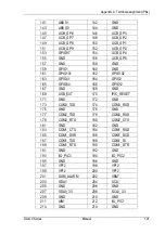


Appendix C: Mechanical dynamic loading
DLoG X Series
Manual
135
21.4.1.
Approximate solution for the selection of elastomer springs
Since
ω
² = c / m we obtain the following relationship:
Whereby:
m
= oscillatory mass
= 5 kg
f
e
= natural frequency
= 20 Hz
c
= spring constant in N/mm
This model applies to the oscillatory mass at the device’s center of gravity. This is
located around 150 mm above the mounting surface of the group of springs and also
displaced from it.
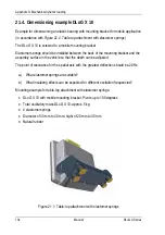
To determine the spring constant for an individual elastomer spring, the leverages and
arrangement of the springs (here in a triangle) must also be considered.
Furthermore, each of the 4 elastomer springs connected in parallel must deliver one
quarter of the total spring constant, i.e., 78 N/mm / 4 = 19.5 N/mm.
Of the six degrees of freedom in which the DLoG X 10 can oscillate, we only consider
those with the greatest deflection for the sake of simplicity. In other words, we observe
the display as it oscillates towards or away from us (a combination of rotational and
longitudinal oscillation).
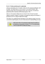
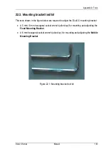
Comparative measurements for precisely the arrangement displayed in
(construction of the mounting bracket, quantity and position of the elastomer springs)
show that the individual spring must be stiffer by a factor of 38 for the mathematical
model stated above to be applied.
Factors for other mountings with elastomer springs must be
calculated through testing!
As a result, this model gives a value of 19.5 N/mm x 38 = 741 N/mm for the required
single spring constant.
mm
N
f
m
f
m
c
e
e
/
78
039
,
0
1000
²
4
2
2
=
⋅
⋅
≈
⋅
⋅
≅
π
Summary of Contents for DLoG X 10
Page 1: ...3 10 DLoG X 7 DLoG X 10 DLoG X 12 Manual ...
Page 3: ......
Page 12: ......
Page 55: ...Initial operation DLoG X Series Manual 43 COM2 Options 13 Audio Option ...
Page 87: ...Boot loader DLoG X Series Manual 75 Figure 9 2 Boot loader diagram 2 ...
Page 109: ...Audio Option DLoG X Series Manual 97 Figure 13 2 Audio port circuit diagram ...


