6 / 16
Subnetwork Bus Topology and EOL Terminations
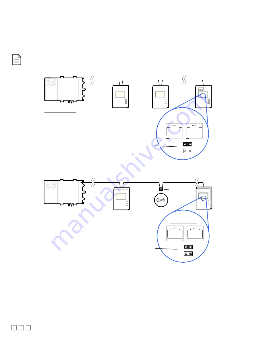
Only a daisy chain topology is acceptable for the room device subnetwork bus. T connections are not allowed.
Some controller models support the connection of other devices to the Subnet Port as part of the Smart Room Control solution (see the controller’s
datasheet for more information).
For non ECB-600 or ECL-600 Series controllers, only the EOL terminations of the last subnetwork bus device are set to ON. All other subnetwork bus
devices must have their EOL terminations set to OFF. The controller must be the first device on the Cat 5e Cable Subnetwork bus as its internal EOL ter-
mination is permanently enabled.
See Table 1 for the number of Allure EC-Smart-Vue sensors that a given controller model can support.
Typical Room Devices
Cat 5e Cable Subnetwork Bus
EOL set to ON
at the last
sensor at the
end of the Bus
ON
E
O
L
OFF
Controller Series:
· ECB-VAV-O
· ECB-VAVS
· ECB-VVTS
· ECB-VAV-N
· ECB-103
· ECB-203 Series
· ECB-300 Series
· ECB-400 Series
Back of Allure
EC-Smart-Vue
· ECL-VAV-O
· ECL-VAVS
· ECL-VVTS
· ECL-VAV-N
· ECL-103
· ECL-203 Series
· ECL-300 Series
· ECL-400 Series
Figure 7: Setting the EOL Terminations on the Allure EC-Smart-Vue Sensor for non ECB-600 or ECL-600 series, non-Smart Room Con-
trol controllers
Typical Room Devices
Cat 5e Cable Subnetwork Bus
EOL set to ON
at the last
sensor at the
end of the Bus
ON
E
O
L
OFF
Controller Series:
· ECB-VAV
· ECL-VAV
· ECLYPSE (ECY-VAV, ECY-S1000)
· ECB-PTU Series
· ECL-PTU Series
Back of Allure
EC-Smart-Vue
ECx Subnet
Adapter
Figure 8: Setting the EOL Terminations on the Allure EC-Smart-Vue Sensor for Smart Room Control-compatible controllers
When one or more Allure EC-Smart-Vue sensors are installed with an ECB-600 or ECL-600 (without an ECx-4xx IO Extension Module), only the EOL
terminations on the ECB-600 / ECL-600 and the last Allure EC-Smart-Vue sensor are set to ON. All other Allure EC-Smart-Vue sensors must have their
EOL terminations set to OFF.


