Dingo K9-4 Operation & Maintenance Manual
22
Dingo K9-4 Operation & Maintenance Manual
23
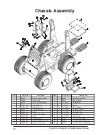
Item Qty Dingo Part No
Description
1
4
610-000-031
Wheel Hub 1 3/8” Centre
2
4
613-000-017
Dingo Tyre Trelleborg
3
20
610-000-030
Wheel Stud 7/16” x 1 7/8” UNF
4
4
330-001-007
Nyloc Patch Nut
5
4
330-001-006
Hydraulic Wheel Motor 1 3/8” Shaft
6
4
330-006-029
K94 Wheel Motor O-Ring
7
20
610-000-027
Wheel Nut 7/16” UNF
8
1
330-003-004
Over Centre Valve
9
12
316-797-500
Hydraulic Fitting (C3-1414)
10
4
316-757-500
Hydraulic Fitting (ZC2-1414)
11
2
K94419
Pipe - Wheel Motor Front To Rear (C5)
12
1
K94416
Pipe - Wheel Motor Front Right Top (C2)
13
1
K94418
Pipe - Wheel Motor Front Left Top (No Relief) (C4)
14
1
K94417
Pipe - Wheel Motor Rear Left Top (No Relief) (C3)
15
1
K94415
Pipe - Wheel Motor Rear Right Top (C1)
16
16
113-522-032
Socket Head Cap Screw-UNC 1/2” x 2”
17
2
310-797-600
Hydraulic Fitting (C26-1414)
18
2
330-003-068
Wheel Motor Relief Valve
19
1
K94436
Pipe - Wheel Motor Rear Left Top (With Relief Valve)C3
20
2
315-797-500
Hydraulic Fitting (C59-1414)
21
1
K94437
Pipe - Wheel Motor Front Left Top (With Relief Valve)
Inner Tank Assemblies
Part Numbers
Summary of Contents for K9-4
Page 24: ...Dingo K9 4 Operation Maintenance Manual 24 Main Control Bank Assembly ...
Page 26: ...Dingo K9 4 Operation Maintenance Manual 26 Remote Control Bank Assembly ...
Page 32: ...Dingo K9 4 Operation Maintenance Manual 32 Yanmar Dash Assembly ...
Page 34: ...Dingo K9 4 Operation Maintenance Manual 34 Perkins Dash Assembly ...
Page 38: ...Dingo K9 4 Operation Maintenance Manual 38 K9 4 Arm Assembly ...
Page 43: ...Dingo K9 4 Operation Maintenance Manual 43 Yanmar Engine Assembly Series I ...
Page 49: ...Dingo K9 4 Operation Maintenance Manual 49 K9 4 Perkins Engine Diagram And Part List ...


