


CLM–36
©
Dinel, s.r.o.
14
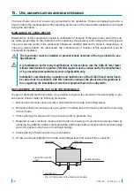
9 . Preparing of level meter for measuring
PREPARING OF LEVEL METER
1. For access to the adjustment elements disconnect a connector and unscrew a nut (attention for
inside connecting wires). Connect the connector again.
2. Connect the level meter to the supply unit through milliammeter (controller, etc.).
3. Set the trimmer
*1)
20 mA into the basic position (this position is set by producer):
a)
Turn the trimmer totally right (clockwise).
b)
Turn the trimmer back about 3 turns left (anti clockwise).
*1) The trimmers are without backstops - approx. 15 turns
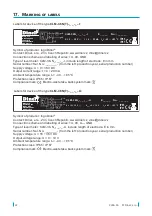
ADJUSTMENT ELEMENTS OF LEVEL METER
Fig. 10:
The top view on the internal electronic module
with current output (variant –I)
DIP switches
(for range select)
trimmer 4 mA
(for compensation
of initial capacity)
trimmer 20 mA
(for sensitive span
adjustment)
BU (-)
BN (+)
GNYE
(Shielding)
brass tie
(for pull out of
electronic module)
DIP switches
(for
range select)
trimmer 0 V
(for compensation of
initial capacity)
trimmer 10 V
(for sensitive span
adjustment)
BU (-)
BN (+)
GNYE
(Shielding)
BK
(Uout)
brass tie
(for pull out of
electronic module)
0V
10V
Fig. 11:
The top view on the internal electronic module
with voltage output (variant –U)
Legend:
GNYE – green-yellow
BU – blue
BK – black
BN – brown


