background image

DNDS Modular     Original Betriebsanleitung      Original Instruction Manual


Sicherheitstechnik  Stand 19.02.2018 


Date 2018-02-19 


Seite 7 von 31 

page 7 of 31 


Ergänzungen nach DIN EN ISO 13849-1 


Die Grenzen des SRP/CS beginnen an den Eingangssig-

nalklemmen und enden an den Klemmen der kontakt-

behafteten Freigabepfade. 


Änderung, Reparatur und Instandhaltungen durch  

Anwender sind nicht erlaubt. Getroffene  

Fehlerausschlüsse gelten unverändert. 


Die Anforderungen unten sind in dieser  

Betriebsanleitung beschrieben: 


Beschreibung der Schnittstellen zu SRP/ CS und  

Schutzeinrichtungen (modulabhängig beschrieben) 

Additions according 13849-1 


The boundaries of the SRP/CS start at the input 

signals clamps and will end at the clamps of the 

contact driven enable path. 


Changing, repair and maintenance by the user is 

not intended. Exclusions of errors made, will stay 

valid unchanged. 


The requirements below are described in this  

instruction manual: 


Description of the interfaces to SRP/ CS and safety 

0equipment (described module dependent) 


Ansprechzeiten Grenzen für den Betrieb  


Anzeigen und Alarme  


Muting und zeitweiliges Aufheben der  

Sicherheitsfunktionen  


Betriebsarten allgemein  


Instandhaltung, Checklisten und Ersatz interner Teile 

(trifft nicht zu) 


Mittel zur leichteren und sicheren Fehlersuche  


Testintervalle (trifft nicht zu)  


Für die notwendigen Angaben siehe Inhaltsverzeichnis. 


Reaction time Limits of operation  


Indicators and alarms  


Muting and temporary disabling of the safety  

functions  


Operation mode’s general descriptions  


Maintenance, Checklists and internal spare parts 

(not valid) 


Tools for easy and safe troubleshooting  


Test intervals (not valid)  


For the necessary information see contents.  


Risikograf zur Bestimmung des PL

r

 für jede  

Sicherheitsfunktion 

Risk diagram to determine the PL

r

 for every safety 

function 


Legende und Risikoparameter 
L

:  niedriger Beitrag zur Risikoreduzierung 

H

:  hoher Beitrag zur Risikominderung 

PL

r

: erforderlicher Performance Level 

S

:  Schwere der Verletzung 

S1

:  leichte (reversible Verletzung) 

S2

:  ernste (irreversible Verletzung, Tod) 

F

:  Häufigkeit und/oder Dauer der  


Gefährdungsexposition 

F1

:  selten bis weniger häufig und/oder die Zeit der  


Gefährdungsexposition ist kurz 

F2

:  häufig bis dauernd und/oder die Zeit der  


Gefährdungsexposition ist lang 

P

:  Möglichkeit zur Gefährdungsvermeidung der  


Begrenzung des Schadens 

P1

:  möglich unter bestimmten Bedingungen 

P2

:  kaum möglich


Legend and Risk parameters 
L:

  low impact on risk reduction 

H

  high impact on risk reduction 

PL

r

 necessary performance Level 

S:

  severe of injury 

S1:

 light (normally reversible injury) 

S2:

 severe (irreversible injury including dead)


F:

  frequency and/or duration of the danger situation 


F1:

  seldom to infrequent and/or short   exposition to 


danger situation 

F2:

 frequent or constant and/or long exposition  


to danger situation 

P:

  possibilities to circumvent the danger or limitation 


of damage 

P1:

 possible under certain conditions 

P2:

 nearly impossible 


H

L

P1

P2
P1

P1

P1

P2

P2

P2

Start

a

b

c

d

e

F1

F2

F2

F1

S1

S2

PLr

Summary of Contents for DNDSmodular

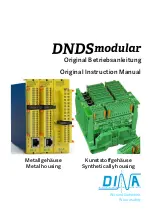
Page 1: ...Original Betriebsanleitung Original Instruction Manual Metallgeh use Kunststoffgeh use Metal housing Synthetically housing Wir sind Sicherheit We are safety...

Page 2: ...utilizan los siguientes est ndares e DIN EN 60947 5 1 2015 05 f DIN EN ISO 13849 1 2016 06 g DIN EN ISO 13849 2 2013 02 Zusatzanforderung Supplementary requirements DGUV Test GS ET 20 2016 10 DIN EN...

Page 3: ...hler und St rungen 12 Faults and Errors 12 Reaktionszeit 12 Reaction times 12 Inbetriebnahme 13 Operation 13 Wiedereinschaltsperre S4 Position 1 und 2 on 13 Restart interlock S4 position 1 and 2 on 13...

Page 4: ...EN 60947 5 1 Part 5 2010 4 Low voltage switch gear and control gear electro mechanical control circuit devices DIN EN ISO 13849 1 2016 06 Safety related parts of control systems Part 1 General princi...

Page 5: ...sten Fehlerfall unbedingt Entsorgen Sie das Ger t nach Ablauf der Lebensdauer sachgerecht Bei nicht Einhaltung dieser Vorschriften akzeptiert DINA Elektronik GmbH keinerlei Anspr che f r die Entstehun...

Page 6: ...Jahr bei Performance Level d angefordert werden Die Angaben in den technischen Daten am Ende dieser Betriebsanleitung m ssen beachtet werden Die Vorschriften des Herstellers der Anlage oder Maschine...

Page 7: ...ion Indicators and alarms Muting and temporary disabling of the safety functions Operation mode s general descriptions Maintenance Checklists and internal spare parts not valid Tools for easy and safe...

Page 8: ...4 3 2 1 5 6 on Modulf hrung Moduleguideway Einstellung am Rack Adjustment at the rack DNDS OM PM PMG GM V1 GMG V1 VM VMG on 6 5 4 3 2 1 DNDS GM GMG Modul links vom GM GMG steuert SPEED2 Module left o...

Page 9: ...IN1 und IN2 am Eingangsmodule angeschlossen Die Montage der Sensoren muss sicherstellen dass im Stillstand mindestens ein Sensor aktiv ist Statusanzeige ber LED Auswahl der max Drehzahlen erfolgt ber...

Page 10: ...inals reduction of the selection at D Terminals 100 25 Switch over between automatic mode Fx at 24V and tool setting function mode F off R1 Terminal To select the semi automatic mode R1 Terminal is on...

Page 11: ...9 on Teiler an 1 8 x 4 S1 S2 P10 off Messsystemfrequenz 50Hz unterdr ckt Einkanalige Messsystemfrequenz 800Hz ist unterdr ckt S1 S2 P10 on Messsystemfrequenz 25Hz ist unterdr ckt Einkanalige Messsyste...

Page 12: ...e divisor For resolver the change of the phase is monitored For incremental system monitored frequency for tool setting 10 20 moni tored frequency for standstill Nicht ben tzte berwachung F r den nich...

Page 13: ...DC Necessary F Terminals connected to 24V via control switch Automatic mode with Input modules with D Terminals only Necessary D Terminals connected to 24V via control switch Tool setting SH Terminal...

Page 14: ...S3 Position 3 4 ON Teiler variabel ON Divisor variable S3 Position 3 4 Off Teiler konstant Off Divisor constant S4 Position 1 2 ON Wiedereinschaltsperre aktiv ON restart interlock active S4 Position...

Page 15: ...minals 24V S6 S7 1 5 2 6 3 7 4 8 1 5 2 6 3 7 4 8 D1 D2 D3 D4 Hz F1 F2 F3 F4 00 100 5Hz 01 150 25 02 200 30 03 275 35 04 355 40 05 400 45 06 450 50 07 500 55 08 550 60 09 630 65 10 700 70 11 800 75 12...

Page 16: ...r Halbautomatikbetrieb und Einrichtbetrieb Siehe Tabelle unten Adjustment of the monitoring Frequency for semi automatic function mode and Tool setting see table down S4 Position 1 2 ON Wiedereinschal...

Page 17: ...5 50 237 59 2 4 5 12 28 100 475 60 2 42 7 17 29 20 110 61 2 50 10 25 30 5 5 50 275 62 2 53 15 38 31 100 550 63 600 Frequenzauswahl f r Vmax bei V7A und V7C Selection of frequency for Vmax using V7A an...

Page 18: ...Geschwindigkeit Selected maximal speed 24V Verbunden mit 24V DC Connected to 24V DC 33 3443 44 ffnen sofort bei V Vmax Open directly at V Vmax 57 5867 68V1 ffnen bei V Vmax nur wenn nach 0 5s V 90 vo...

Page 19: ...11 50 43 180 11 22 43 7 5 12 125 44 450 12 24 44 7 5 13 240 45 200 13 26 45 7 5 14 40 46 500 14 28 46 7 5 15 100 47 15 30 47 7 5 16 250 48 300 16 32 48 7 5 17 480 49 17 34 49 7 5 18 65 50 360 18 36 5...

Page 20: ...der berwachungsfrequenz f r Halbautomatikbetrieb und Einrichtbetrieb Siehe Tabelle unten Adjustment of the monitoring Frequency for semi automatic function mode and Tool setting see table down S4 Posi...

Page 21: ...Vmax Gew hlte maximale Geschwindigkeit Selected maximal speed 24V Verbunden mit 24V DC Connected to 24V DC 33 3443 44 ffnen sofort bei V Vmax Open directly at V Vmax 57 5867 68 V1 ffnen bei V Vmax nur...

Page 22: ...31 28 1 70 25 63 Frequenz Auswahl f r Vmax bei 1R 1RG V2 V3C Selection of Frequency for Vmax using 1R 1RG V2 V3C Auswahl von Vmax im Einricht und Halbautomatikbetrieb Auswahl von Vmax Selection of Vm...

Page 23: ...SPEED1 33 34 43 44 close directly if V 90 of Vmax LED right is green Usage start of the brake action of the drives See restart interlock LED at PMG PM LED left and right are dark without measuring sys...

Page 24: ...in case of fault the delay time can be shortened or the contacts open at once All contacts close again 57 58 67 68 with 250ms time delay if at all input modules V 90 of Vmax Terminals E1 E2 and Q con...

Page 25: ...1 13 12 14 21 23 22 24 68 67 58 57 E1 E2 Q 24VDC Not Halt Kreis Emergencystop circuit Schutzt rschalter Protectioncover switch Quit Maschinennetz Machinenet Netz Net T r entriegeln Cover unlock STOP S...

Page 26: ...GM GMG V1 0V STOPSPEED UB 68 67 58 57 24 23 14 13 SPEED2 STOP A1 33 34 43 44 SPEED1 A2 24V DC A1 24V DC 0 5A A2 0V DINAELEKTRONIK D 72649WOLFSCHLUGEN ID No 10GM0 DNDSGM 1ZD7 USLISTED IND CONT EQ R L U...

Page 27: ...0 von Vmax V nach 0 5s gr er 90 von Vmax V during 0 5s less than 90 of Vmax V after 0 5s bigger than 90 von Vmax V 100 60 V 90 Vmax 33 34 43 44 57 58 67 68 40 20 t tr V 100 60 33 34 43 44 57 58 67 68...

Page 28: ...3 F2 F2 F1 F1 F3 F4 F4 IN1 IN2 D1 D1 D2 D2 D3 D3 D4 D4 R1 SH 1 5V 1VSS 1Vpp 300KHz SPEED STOP ON verriegelt locked entriegelt unlocked 104mm Metall Metal Kunststoff Synthetically Rack Varianten Gewich...

Page 29: ...tern Minimal 1 25A Maximal Leitungsschutz Betriebstemperatur DIN IEC 60068 2 3 10 60 C Lagertemperatur DIN IEC 60068 2 3 40 85 C H henlage des Einsatzes 2000m ber NN R ttelfestigkeit in allen 3 Ebenen...

Page 30: ...tion Operating temperature DIN IEC 60068 2 3 10 60 C Storage temperature DIN IEC 60068 2 3 40 85 C High of the usage location 2000m over sea level Vibration tolerance on all 3 levels Sinus 10 55Hz 0 3...

Page 31: ...Instruction Manual Sicherheitstechnik Stand 19 02 2018 Date 2018 02 19 Seite 31 von 31 page 31 of 31 wir sind sicherheit DINA Elektronik GmbH Esslinger Str 84 D 72649 Wolfschlugen Phone 49 7022 9517...

Reviews: