DNDS Modular Original Betriebsanleitung Original Instruction Manual
Sicherheitstechnik Stand 19.02.2018
Date 2018-02-19
Seite 30 von 31
page 30 of 31
Technical Data
Operating voltage U
B
24 V DC
Voltage tolerance U
B
90 - 110%
Residual ripple U
B
(DC)
max 10 %
Power consumption at
U
B
max 10 W
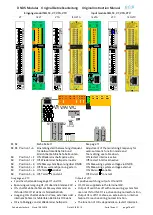
Safety contacts
STOP all output modules
SPEED 1 all output modules
SPEED 2 at GM and GMG
SPEED 2 at GM V1, GMG V1, VM and VMG
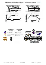
Typical response time/ fall-back time of the contact output
≤
15ms
Contact material
5µm Au
Minimal switch current
10mA
Switching capability according to DIN EN 60947-4-1/DIN EN 60947-5-1 DC1: 24V/ 6A, DC13: 24V/ 4A, 0.1Hz
Switching capability according to DIN EN 60947-4-1/ EN 60947-5-1
AC1:250V/ 6A, AC15: 230V/ 3A, 0.1Hz
Sum current from all contact
≤
12A
Contact life DC13: 24V/ 1A
1.5x10
5
Contact life DC13: 24V/ 4A
10
4
Contact life AC15: 230V/ 0.5A
2x10
6
Contact life AC15: 230V/ 1A
3x10
5
Mechanical contact life
> 50x10
6
Maximal cycles DC13: 4A
360 cycles /h
Maximal cycles AC15: 1A
360 cycles /h
Contact fuse
6A slow
Short-circuit strength
200A/ B6 automat
800A/safety fuse 6A gl
Maximum contact voltage
250V AC
Surge voltage strength, use in pollution degree 2 Environment.
4KV
OS, OD, O1, O2
0,1A
Operating time
100 %
Internal unit fuse protection
Minimal 1,25A, Maximal: Conductor protection
Operating temperature DIN IEC 60068-2-3: -10
→
+ 60°C
Storage temperature DIN IEC 60068-2-3: -40
→
+ 85°C
High of the usage location
2000m over sea level
Vibration tolerance on all 3 levels
Sinus 10 – 55Hz, 0.35mm, 10 cycles, 1 Octave / min
Maximal frequency at the RJ45 connector
300KHz
Maximal Frequency at the RJ45 connector
800Hz modulation, 10KHz carrier
Maximal frequency at IN1 and IN2
1500Hz
Repetition accuracy
±
0,1 %
Temperature dependency of the trigger point
0,02 %/°C
Air gap creep age to
VDE 0110 Teil1
Max. lead cross section
Core with crimp connector
Input terminals:1 x 1,0 mm
2
,
Output terminal: 1 x 1,5 mm
2
Connection wire
60/75°C copper
Terminal
Spring load terminals, pluggable
Housing metal material
Hosing synthetically material
Sheet steel, powder-coated
PVC, PC, PA / VO (UL94)
Protection Only for
housing and terminals: IP20,
cabinet mounting with minimal protection IP 54
Contact durability
24V DC switching voltage: work days every year: 260, 8h every day
Load:
Switch current:
Switch cycles
DC1
1A
384
192
96
DC13
1A
15
7
3.6
DC1
4A
192
96
48
DC13
4A
1
0.5
0.25
DC1
6A
153
76
38
Years
5
10
20
AC1:
control of non-inductive or low inductive load AC voltage
AC15: control of inductive load AC voltage
DC1:
control of non-inductive or low inductive load DC voltage
DC13: control of inductive load DC voltage
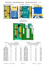
13 1423 24
33 3443 44
53 5463 64
57 5867 68
10
S
chal
ts
pi
el
e
/ C
yc
les
Schaltstrom (A) / Switching current (A)
DC13
24V
AC15
230V
AC1
230V
DC1
24V
7
10
6
10
5
10
4
0.1
0.5
1.0
2.0
3.0 4.0 5 6 10


