background image

GGGGGGGGGGGGGGGGGGGGGGGGGGGGGGG

G

52 


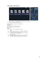
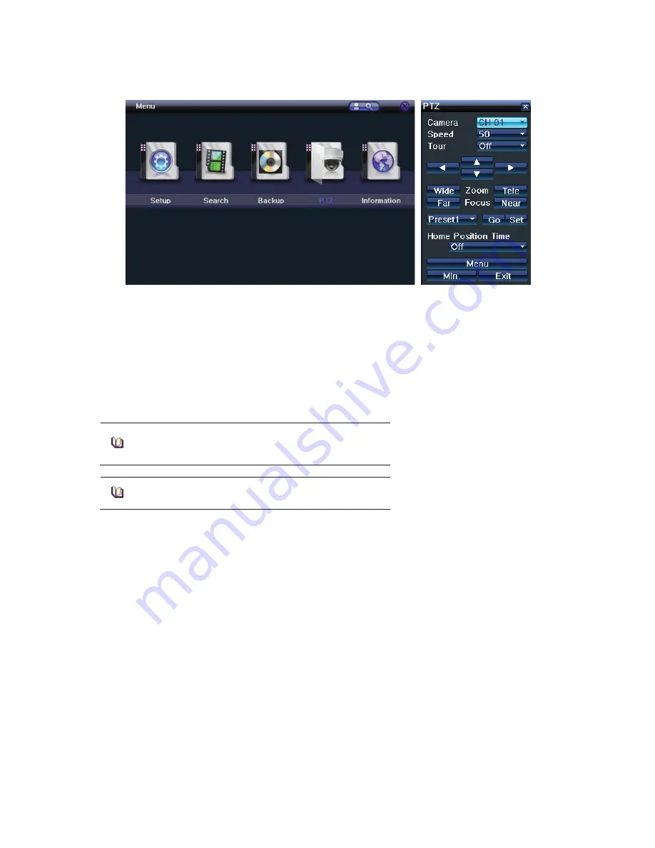
Controlling a PTZ Camera 


To control a PTZ camera, go to 

[Menu] > [PTZ]

 or press PTZ button on the remote controller. 


Select Channel of the PTZ camera you wish to control.  

 
Direction Keys: Adjust the PTZ camera to look at a different scene.  
Wide: Zoom Out 
Tele:  Zoom In  
Min. / Max.: Change PTZ controller to Min or Max mode.  
Speed: 1 ~ 100; Adjust the speed of the PTZ camera.  
Tour: Off, 1, 2 
Preset: 1 ~ 8 
Home Position Time: Off, 1, 4, 10, User Defined (1 ~ 60 minutes)


Preset

.  

Using the Horizontal, Vertical, Zoom, Focus features of the PTZ camera, 
view a specific spot of the image. Designate that spot as a preset and 
move to the preset quickly and automatically. 


Home Position Time 

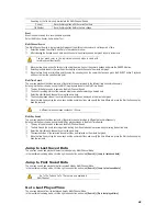
Preset 1 is set as the Home Position. If there are no signals to the PTZ 
camera after a certain time, it will automatically go to the home position


Summary of Contents for VMAXD1 16

Page 1: ...G ...

Page 2: ...reakdown install the DVR away from magnetic materials When using a rack other than the standard one use a separate table with sufficient spacing i e 60cm from the floor 50cm from the ceiling and 20cm from the side and back walls and other objects Safety Notes on the DVR When installing additional boards and HDD separate the power cable and completely turn off the power supplied to the DVR Keep the...

Page 3: ... 11 Time 12 Camera 14 Recording 20 Schedule 25 Disk Configuration 26 Network Configuration 28 System 33 5 LIVE 36 Real Time Live View 36 Status Icons 37 Control Bar 37 System Login 38 System Logout 38 Screen Division and Auto Sequence 39 Zoom 40 Instant Recording 40 6 SEARCH 41 Express Search 41 Jump to Last Saved Data 42 Jump to First Saved Data 42 Go to Last Played Time 42 7 PLAYBACK 43 Playback...

Page 4: ... Version 53 System Log 54 Miscellaneous Control 55 Monitor Configuration 56 Channel Grouping 56 11 REMOTE ACCESS 57 Features 57 Connection 57 Live Mode 58 Playback Mode 59 Management 59 12 DNA 61 Setup 61 User Interface 63 Configuration 64 Playback 66 Control 68 Event 69 13 RAID 70 Configuring RAID 70 Destroying RAID 71 APPENDIX 72 Recommended HDD Specification 72 Recommended PTZ Camera Protocol 7...

Page 5: ... Resolution HDMI Full HD 1920x1080 WSXGA 1680x1050 SXGA 1280x1024 VGA WSXGA 1680x1050 SXGA 1280x1024 BNC SDTV 720x480 576 POS ATM Interface 8 RS232C Simplex Terminal Block 4 RS232C Simplex Terminal Block Backup Copy Access eSATA DVD RW USB2 0 Network Network Access Ethernet 10 100 1000 RJ45 PTZ Controller Access RS485 Half Duplex Terminal Block Internal HDD Internal ODD SATA HDD Max 4ea SATA Type ...

Page 6: ...16 Sensor Input 4 Sensor Output for 16 Channel Time Server Function NAS Network Attached Storage Backup Over Ethernet Multi User Access Covert Channel Network Bandwidth Control Watermark Verification Digital Signature Verification Go To Multi Date Time Calendar Smart Panorama and Log Viewer Search Smart Web Viewer for Live Playback Backup Configuration Remote Setup Backup and Relay Control Mobile ...

Page 7: ...ptical Device Bay Door for CD ROM 6 Functional Buttons Shortcut keys for the indicated function 7 Directional Button and Select Key Use instead of mouse control Rear Panel View No Name 1 Power Supply 2 Camera Input Loop Output Audio Input Spot Output 3 USB Connection USB2 0 e SATA 4 Configuration Dip Switch NTSC PAL Monitor Out 5 RS232C for Console Output 6 Ethernet Port 7 VGA Output 8 HDMI Output...

Page 8: ...itor to VGA OUT on rear panel and HDMI monitor to HDMI on rear panel On VGA and HDMI Output only the channel title is shown For higher resolution greater than HD only VGA Output is available ཟ Connect Spot Monitor to SPOT on rear panel འ The following devices can also be connected Devices DVR Terminal Internal Hard Drives 6 SATA Spot Monitor 4 BNC for 16 Channel 1BNC for 8 Channel Audio Each Chann...

Page 9: ...TZ camera Sensor Connection Depending on the model connect the sensor to the terminal blocks S1 S16 Each input terminal is connected relatively with the channel number Sensor and Relay Type NC Normal Close Normally Closed opens when a signal is received NO Normal Open Normally Open closes when a signal is received Relay Connection Relay the output signal to external devices such as Alarm and Siren...

Page 10: ... Normal Close Normally Closed opens when a signal is received NO Normal Open Normally Open closes when a signal is received Mouse The mouse pointer as shown below appears if a mouse is connected to the USB terminal located at the front panel MOUSE CONTROL FUNCTIONS Click Right Button Monitoring Mode Move from Monitoring Mode to Monitoring Setup Open or Hide Play Menu Show Submenu of the certain Se...

Page 11: ...ress Setup button on the front panel ID and Password are required for initial installation Default ID and Password are shown below Local Admin 00000 User1 1111111 User2 2222222 User3 333333 User4 4444444 To change the password right click on mouse and click Setup System Admin Password 4 SETUP ...

Page 12: ...or automatic NTP setup set Server Type to NTP and Server URL as Auto NTP setup is only available when Time Sync has been set to NTP The user can enter the IP only when the server type is DVR Date Time If Time Sync is set to OFF set the date and time manually Use the mouse or the arrow keys and the SELECT button to set the Year Month Day Hour Minute and Second on Date Time To complete the setting c...

Page 13: ...y setting in the Start Time and End Time fields set Day to 0 After the DST has been selected the existing data will display as OLD_ in the search and log list Auto Reboot To help keep your system healthy configure your VMAXD1 to reboot automatically Use your mouse to set the Auto Reboot to ON or OFF Select the exact time for Auto Reboot and select the day of the week you wish to perform Auto Reboo...

Page 14: ...y screen is black data is still being recorded and saved depending on the recording schedule PZ Mask Used to hide a certain area of the real time monitoring screen To setup the PZ Mask Area move cursor above the PZ Mask field for the channel you wish to set and click the left mouse button The channel will be displayed with grid lines Select the blocks you wish to mask by clicking and dragging the ...

Page 15: ...erent presets Configure up to two Tours and each tour can have up to 8 presets If a tour has been set set the Duration for the staying time when the tour is activated POS To setup a Point of Sale POS device connect the POS device to the Terminal Block connection for RS232C Go to Setup System Sensor POS Port and select POS 1 8 Go to Setup Camera POS and select the protocol baud rate and character c...

Page 16: ...GGGGGGGGGGGGGGGGGGGGGGGGGGGGG 16 When the POS device has been configured setup the VMAXD1 to record any transactions sent from the POS device Go to Setup Recording Recording and make sure Text is set to ON ...

Page 17: ... Use the Playback Control Bar to playback the video ཞ To move to the next or previous POS search result use directional keys on the front panel or use the mouse and the control bar During playback user can choose to display or hide the POS transaction on the recording video ཛ To hide the POS transactions click the right mouse button during Playback Mode and move the mouse cursor above Text View ཛྷ ...

Page 18: ...h to disable motion detection Areas where motion detection is disabled will be indicated in the color brown Select Motion Area of each channel When clicked the single channel mode composed of square boxes appears on the screen Use the mouse to select areas you wish to disable motion detection Areas where motion detection is disabled will be indicated in the color brown Once motion area has been se...

Page 19: ... is normally open closes when a signal is received NC which is normally closed opens when a signal is received Relay Output Connection Relay output signal to external device such as Alarm or Siren Connect relay to R1 R2 R3 and or R4 of the terminal block located on the rear side with R _Com Port Number of relay varies depending on the model of the DVR ...

Page 20: ...o Pattern Text Set the event as ON to record when the type of event occurs If you do not wish to record set as OFF All Event recording follows the Event Speed which can be configured at Setup Recording Event Speed See 5 3 2 Recording If none of the event options are turned ON the VMAXD1 will record continuously Event Type Description Continuous The VMAXD1 will record continuously at the Normal Spe...

Page 21: ...ded channels Select from Lowest Low Middle High and Highest ଖ The higher the quality the larger the file size will be Normal Speed When there is no event the VMAXD1 will record with this frame rate Event Speed This will be the recording frame rate for Event Recording Sensor and Audio MODEL CIF NTSC PAL 2CIF NTSC PAL 4CIF NTSC PAL VMAXD1 16 480 400fps 480 400fps 480 400fps VMAXD1 8 480 400fps 480 4...

Page 22: ...to the selected preset E mail When an event is triggered the VMAXD1 will send user an e mail Setup your email at Setup Network Config E mail Relay When an event is triggered relay out will be activated Spot When an event is triggered user will receive popup on spot monitor Popup In real time recording mode a Warning window will appear This window will inform the user when an event occurs Callback ...

Page 23: ... seconds before the event occurrence Post Alarm Set the duration you wish the VMAXD1 to record immediately after the event has ended Select from 5 10 15 20 50 100 and 300 seconds Log Set the VMAXD1 to generate and save specific log categories Motion Sensor Sound Pattern and Text If set as ON the VMAXD1 will save the logs of that category ...

Page 24: ...of the files that need to be saved by adjusting the quality of the image Select from CBR or VBR CBR will give you consistent file sizes but different image qualities VBR will give you consistent image qualities but different file sizes CBR and VBR can be set in 5 different levels depending on the recording quality ...

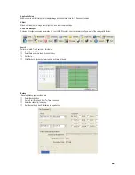
Page 25: ...apply the configuration to Hour Button Select all days and time Day Mon Hol Button Select Horizontal Line Time 0 23 Button Select Vertical Line Holiday This feature enables the user to set the holidays and schedule independently Select Schedule Holiday On the Holiday Registration window select the date by using the arrow keys then press the SELECT button After setting the holiday click Save at the...

Page 26: ...ut they can be transferred into Recording or Backup Select storage in the New category and click the left mouse button Then select Record Init or Backup Init Record Init Transfers the selected storage from New to Recording Backup Init Transfers the selected storage from New to Backup At least one of the storage should be sent to Recording Otherwise recorded data will not be stored in real time Rec...

Page 27: ...ate is not related to a DVR problem The DVR has detected the fault and stopped the recording If there is an active storage device with a warning or a fault a message is displayed on the upper left corner of the screen Instructions for Adding the Local Storage Device Open the system body and install a new disk Connect the data cable and the power cable Connect power to the system and boot the syste...

Page 28: ...twork TCP IP Uses a fixed IP in the Local Area Network environment Go to Setup Network Config Network Check the box to use TCP IP Enter the IP Address Subnet Mask Defualt Gateway Primary DNS and Secondary DNS Click Save ADSL Uses the user authentication type ADSL communication environment Check the box to use ADSL Enter the Username and Password Click Save ...

Page 29: ...e registration procedure of the DDNS host domain name proceeds automatically You can enter a host name that consists of 4 20 letters If the host name you enter has been pre registered in the DDNS server it will not work The basic host name is the MAC address of the DVR If the host name you entered begins with 000c28 none of the MAC addresses will work except those pertaining to that IP address If ...

Page 30: ...default value is 80 If 80 is blocked use a random number over 2000 UPnP Auto Port This is used to connect the VMAXD1 to the network using a router E mail Set your VMAXD1 to send e mail notifications automatically when an event occurs Go to Setup Network Config E mail Check Address field and enter e mail address To attach an image with the e mail check Still Image Attachment Enter sender s email ad...

Page 31: ...twork Bandwidth Limitation Set a limit to the bandwidth that is used when sending data over the network The VMAXD1 will meet this limit by adjusting the image resolution and image quality Image Resolution Adjust the resolution of the image Select from CIF 2CIF 4CIF HCIF QCIF Image Quality Adjust quality of the image A higher value has a higher compression and transmission rate but a lower image qu...

Page 32: ...lback Server IP Port Number User ID and Event Type For the Callback Server IP user can enter an IP or a URL The port number should be over 2000 and should not overlap with the set values at Setup Network Client Configuration The user can select one of the registered users at Setup System Users Select the Transmission Codec JPEG or H 264 for remote transmission Enable or disable mobile connection T...

Page 33: ...n ID For Key Controller To use keyboard controller this ID must match the Keyboard Controller ID If not the keyboard controller will not be able to send input signals to the VMAXD1 The numbers 1 255 can be used as the ID Go to Setup System In the ID for Key Controller selection window enter ID with the arrow keys and the SELECT button The numbers 1 255 are available for ID Users Add Modify or Dele...

Page 34: ...e selected file are displayed Select a file and Firmware Upgrade window will appear ଖ Downgrading to a previous version is not supported ଖ The Upgrade Information window will then appear within 15 seconds Read the information and select Yes to start the upgrade gradually Select No to return to the System Mode After the upgrade is completed the system reboots To check the Firmware Version right cli...

Page 35: ...eys and the SELECT button Select from Latch 5 SEC 10 SEC and Custom 5 60 Auto Log Off This is used to set a time for when the DVR automatically exits the Setup Menu and displays the real time monitoring screen due to inactivity Go to Setup System In the Auto Log Off selection window select the time you wish to set using the arrow keys and the SELECT button Off Auto Log Off is not used ଖ The user c...

Page 36: ...GGGGGGGGGGGGGGGGGGGGGGGGGGGGGGGG 36 Real Time Live View After booting is finished Audio Recording Status Channel Title Connection Status Time and HDD Status are all displayed 5 LIVE ...

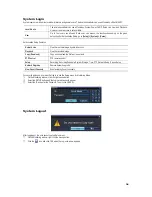
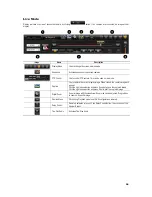
Page 37: ... been stopped G Recording Mode Video Recording Audio Recording Text Recording G Recording Mode Icons distinguish recording status Monitoring Mode Video is not connected or Video is covert Audio is set activated Audio is set as silent No Signal Camera has been disconnected Control Bar ཛ DVR ID ཛྷ Full Screen ཝ 4 Channel Screen ཞ 8 Channel Screen ཟ 16 Channel Screen འ Zoom ཡ Auto Sequence Mode ར Date...

Page 38: ... access Playback View the recorded image Copy Download Copy and download the file from the network PTZ Control PTZ camera control Setup Recording Recording Schedule System Storage Time PTZ Network Setup Screen Setup Network Upgrade Remote network upgrade View Covert Channels Enable viewing Covert channels For security purposes user must first log in to use the Setup menu for Monitoring Mode ཛ On t...

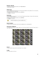
Page 39: ... Group User can view an image as full screen by double clicking a desired channel in the 4 9 or 16 Screen Division Mode Mouse Double click on a channel to move to Big or Biggest Screen Division Mode of the selected channel number Auto Sequence is used to rotate images in 1 4 9 Big or Biggest Screen Division Mode after a certain period of time Auto Sequence is not available in the 16 Screen Divisio...

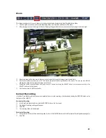
Page 40: ...ft click and drag the yellow box to magnify the image more than x4 ཟ If using the remote controller and or front panel zoom in 3 levels by clicking the SELECT button on the remote controller or the SELECT button on the front panel Use the arrow keys to shift the yellow box Instant Recording In the Real Time Monitoring Mode the user can instantly start or stop the recording of all channels by click...

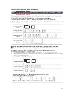
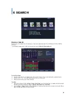
Page 41: ...s in the calendar indicates that recorded data exists ཛྷ Select the Hour 0 23 The recorded data will appear in the form of a bar graph Select an area on the bar graph to select the Minute Time Index ཛ When the user changes the time at Setup Time Date Time a new folder titled Index is created and the files saved in the folder before the time change can be found at Setup Express Search Time Index ཛྷ S...

Page 42: ... and channel by using the arrow keys ཞ The hourly displayed video of the selected channel will then be displayed in the minute bar graph ཟ Move the time line by using the arrow keys and the numeric buttons and specify the time Afterward press the Start button and play back the contents A different time zone means continuous 16 hours Multi Day Search The user can playback the video contents of the ...

Page 43: ...to the end the data of the next time zone will be automatically searched and played This function is possible only in the Multi Channel Playback mode Both backward playback and forward playback are possible ཝ Using the buttons the user can adjust the playback speed by x1 x2 x4 or x30 No Name Description 1 Channel Mode Change Just like the Live Mode Screen Division Modes are available in the Playba...

Page 44: ... the beginning all pixels are selected Designate an area by clicking the left mouse button and dragging the mouse pointer ཝ Repeat the previous step to select another area ཞ Click the right mouse button to specify the type of smart search you wish to perform Smart Search detects motions in non designated brown blocks ཟ When the settings are completed click the Playback button to begin the Smart Se...

Page 45: ...tain channel for different dates simultaneously The search results are ordered from the oldest to the most recent videos Click the right mouse button during Playback mode and select Multi Day View Search for more details For Multi Time and Multi Day only 1 channel is available at a time Multi Channel This playback feature simultaneously plays recorded videos of multiple channels for a certain desi...

Page 46: ...ture and backup an image onto a CD or an External Device Backup Save the image onto a CD or External Device Snapshot Capture and save the displayed screen Zoom Move to Zoom Mode See Live for more details De Interlace Ally de interlace to the image ...

Page 47: ...ge device such as HDD CD and DVD via the USB 2 0 port For supported external devices refer to APPENDIX The user can backup data in the real time monitoring search log or playback mode VMAXD1 also features NAS Network Attached Storage Backup User can backup data in real time monitoring search log or playback mode 8 BACKUP ...

Page 48: ...nd for To The last 2 digits are determined by the number of folders in the selected device Changing the backup time causes the name of the directory to be backed up to be changed as well འ If the file to be backed up exceeds the free space its size is displayed in a yellow box in case the selected device is capable of rerecording and in a red box if not If the backup storage device is not formatte...

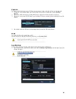
Page 49: ...window for selecting the device will be displayed ཞ If the selected device is an ODD device a prompt asking whether to backup in the ODD device will appear Print The user can print the current displaying image and GUI Right click mouse button during real time monitoring mode then go to to Backup Print A print using PS POST SCRIPT is recommended Log Backup This is to backup system logs These logs i...

Page 50: ...own below Saved as the name below ྙModel ྚ DVR name ྛ Version ྜ Date ྜྷ Time ཝ Go to Setup System Upgrade Setup after you insert the backup device ཞ Now the user can easily upgrade a new device with the current setup values NAS Backup The feature transmits a data from the DVR to backup network devices Right click mouse button during real time monitoring mode then go to to Backup NAS Backup The NAS ...

Page 51: ...manual Select Setup Camera PTZ ཛྷ Configure the Protocol ID Baud Rate Duration and or Tour Baud Rate can be selected at 2400 4800 9600 19200 or 38400 Duration can be selected at 5 10 15 20 5 60 User Setting seconds Tour consists of Tour 1 and Tour 2 Each tour can be set with 8 Presets VMAXD1 Series supports 21 protocols for PTZ control For a list of supported protocols refer to APPENDIX at the end ...

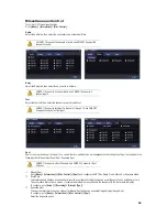
Page 52: ...Z controller to Min or Max mode Speed 1 100 Adjust the speed of the PTZ camera Tour Off 1 2 Preset 1 8 Home Position Time Off 1 4 10 User Defined 1 60 minutes Preset Using the Horizontal Vertical Zoom Focus features of the PTZ camera view a specific spot of the image Designate that spot as a preset and move to the preset quickly and automatically Home Position Time Preset 1 is set as the Home Posi...

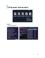
Page 53: ...GGGGGGGGGGGGGGGGGGGGGGGGGGGGGGGG 53 Version Displays all the general system information Go to Menu Information Version 10 System Information ...

Page 54: ...izes the event type User can select the different categories to display the logs of the specific category All Logs related to all system operations All categories will be displayed Fail Logs related to system operation failures including signal loss and network connection failure Network Logs realted to network operations including Network Login Network Logout and Network Live Rec Event Logs relat...

Page 55: ...or a certain function and Spot has an independent monitor and output Spot is prioritized in the following order Manual Spot Event Spot Sequence Spot VMAXD1 16 supports 4 Spot Channels and VMAXD1 8 supports 1 Spot Channel ཛ Manual Spot Go to Menu Information Misc Control Spot and configure the SPOT as Single Quad 4xQuad or Sequence Mode ཛྷ Event Spot This feature quickly displays a channel that is s...

Page 56: ...TV OUT screen by moving it Up Down Left and or Right Excessively moving the screen up down left or right may cause black or gray areas to appear on the display screen The level at which such condition does not occur is based on the proper control range of the monitor Channel Grouping Channel Grouping is used to switch the channel locations in the Monitoring Mode ཛ On the real time monitoring scree...

Page 57: ...apture Digital Zoom PTZ Control Preset Movement Remote Detail Setup Connection ཛ Open Internet Explorer and enter the IP Address for your VMAXD1 ཛྷ Select PC or Mobile Web Viewer ཝ Enter the Port 2000 Username and Password User Name User1 Password 1111111 ཞ For PC Web Viewer click OK button to login For Mobile Web Viewer click LOGIN button PC Web Viewer Login Mobile Web Viewer Login 11 REMOTE ACCES...

Page 58: ...re Use to capture the current display image When clicked the capture image will appear Click the right mouse button and press Save As to save the captured image Click the right mouse button and press Print to print the captured image Digital Zoom Zoom in image with thumbnail view Zoom size can be adjusted Drag red box to zoom on a specific image Remote Menu Click during Playback mode to set DVR co...

Page 59: ...nd time first and then click the Calendar Icon The system will begin playing from the selected data and time 6 Control Button and Adjust Bar Use when playing back recorded videos 7 Volume Control Adjust the audio volume Management User can remotely manage the VMAXD1 During Live Mode just click the Management button The Management Button features the following DVR Setup Application Setup Adjust DVR...

Page 60: ...ormation like your VMAXD1 system User can remotely configure most of the settings with this tool Search Perform a Date Time Search with this feature ཛ Select Search button ཛྷ Select Date and Time then Click Next button ཝ Set Minute ཞ Click Playback Playback of selected date and time will begin Backup Remotely backup your recorded data ཛ Select Backup button ཛྷ Set the Start From and End To Time for ...

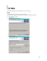
Page 61: ...tall DNA Remote Client Software on your PC for powerful remote client features We recommend all users to download DirectX 9 0 before installation To install DirectX 9 0 go to http www microsoft com ཛ Insert the included CD in your client PC ཛྷ Select DNS msi file ཝ The following window will appear Press Next ཞ Select User and press Next 12 DNA ...

Page 62: ...GGGGGGGGGGGGGGGGGGGGGGGGGGGGGGGG 62 ཟ Installation will begin Press Close when it is completed ...

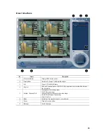
Page 63: ...Software 4 Site List DVR and Cameras listed on DVR CH DVR s registered as a favorite will be listed on the Favorite list 5 Settings Save and Print Configuration Enter Setup menu Print Print current page Snapshot Capture and save current video image Rotate Rotate images Sequencing Log in Log Out 6 Mode Switch from live playback control or event mode 7 Pause Stop and resume a video 8 Message Send a ...

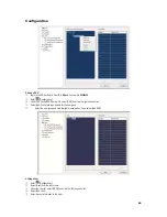
Page 64: ...ra list select DVR and click the right mouse button ཞ Select Add Group and type a name for the new group ཟ Select the new group and click the right mouse button Then select Add DVR Adding a User ཛ Enter Configuration ཛྷ Select User from the left column ཝ Under the User list select USER and click the right mouse button ཞ Select Add User ཟ Enter the user information to the right ...

Page 65: ...DVR ཛ Enter Configuration ཛྷ Select User DVR Assignment from the left column ཝ To grant access to the DVR drag and drop the registered DVR in the middle column to the User s you wish to give access to ཞ Select Add User ཟ Enter the user information to the right ...

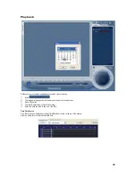
Page 66: ...endar will appear Select the date which has the recorded video ཝ Press OK button ཞ The results will display in Open File window ཟ Select the data you wish to see and click OK Time Date Search View the results as a timeline by clicking Time Date Search tab on the top of the window User can easily select a different date and time ...

Page 67: ...GGGGGGGGGGGGGGGGGGGGGGGGGGGGGGGG 67 Remote File Recorded videos for the searched date will appear Each line represents one hour time increments ...

Page 68: ...DVR such as connected cameras motion detection sensor input alarm output and logs The logs are separated into the categories All Fail Network Record and Normal Through Control you can enter the setup configuration on your connected device Setup pages will differ according to the device ...

Page 69: ...GGGGGGGGGGGGGGGGGGGGGGGGGGGGGGGG 69 Event Event page displays current incoming event s User can play the event as a playback ཛ Select a specific event ཛྷ Right click mouse button and click Play ...

Page 70: ...aid 5 Creation Press OK to initialize RAID When completed RAID will move to Recording tab To check the configured RAID information go to Recording tab Then select the RAID and click RAID Info Resync This will occur when synchronization is broken by unexpected power failure During this process resolution would be restricted to CIF at 120fps Recovery The VMAXD1 will synchronize again when RAID confi...

Page 71: ... to return to normal recording from RAID configuration Right click VMAXD1 and go to Setup Disk Config Recording Select the RAID you wish to destroy then click RAID Destroy If RAID Destroy is not selectable select Offline first Click YES when the popup window appears ...

Page 72: ... SYSTEM CRR 1600i s CRR 1600i s GE GE GE_KARATEL GSP GSP CYBERSCAN_1 HITRON FASTRAX2 FASTRAX2 HONEYWELL SCANDOME2 HSDN 251 LG LG LG_MULTIX LG_OLD MIKAMI MIKAMI MIKAMI ORIENTAL ORX 1000 ORX 1000 PANASONIC WVCS854 WVCS854 PELCO PELCO PELCO D PELCO P PHILIPS PHILIPS PHILIPS PROLINE PROLINE PROLINE_UK RIFATRON RIFATRON 1 RIFATRON SAMSUNG TECHWIN SAMSUNG SPD 1600 SCC641 SUNJIN SUNJIN SUNJIN VICON VICON...

Page 73: ...G ...

Page 74: ...GGGGG G 5436 W Crenshaw Street Tampa FL 33634 Toll Free 866 446 3595 Tel 813 888 9555 Fax 813 888 9262 www Digital Watchdog com technicalsupport dwcc tv Technical Support Hours Monday Friday 8 30AM to 8 00PM Eastern Standard Time ...

Reviews: