DIGITAL SYSTEMS ENGINEERING DVE10VR2 User Manual Download Page 1

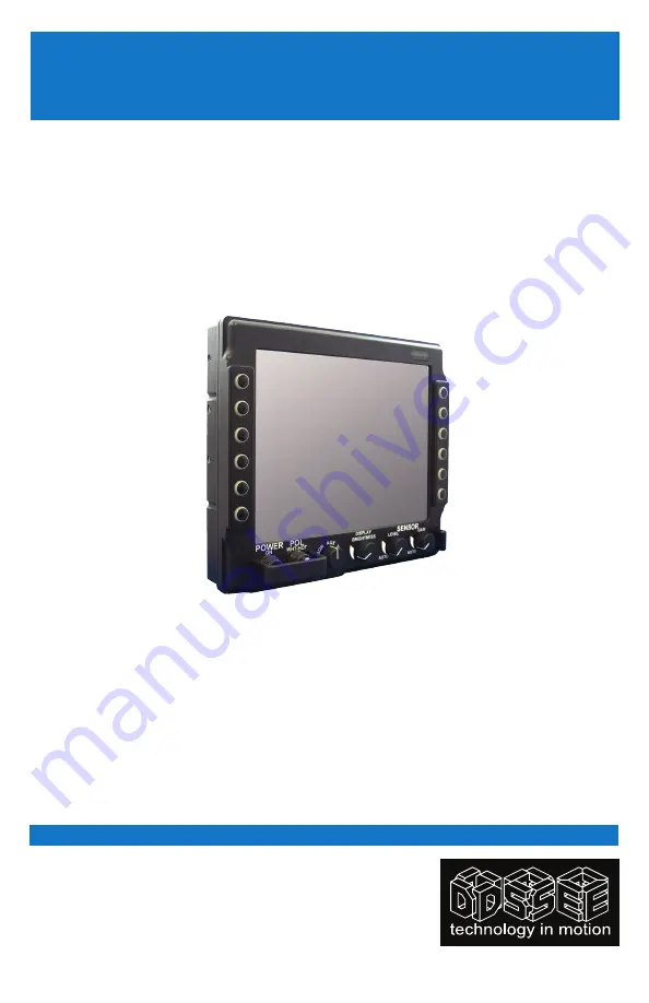
10.4" TFT rugged LCd dispLay

DVE

10VR2


USER MANUAL

DIGITAL SYSTEMS ENGINEERING, INC. (DSE)

17491 NOrTH 93rd sTreeT 

|

 sCOTTsdaLe, aZ 85255 

DSE SERVICE CENTER:


480-515-1110

[email protected] 

|

 WWW.DIGITALSYS.COM 

© 2017 by digiTaL sysTems eNgiNeeriNg. aLL rigHTs reserved.

DRIVER’S VISIoN ENhANCER MoNIToR SERIES

Summary of Contents for DVE10VR2

Page 1: ...DIGITAL SYSTEMS ENGINEERING INC DSE 17491 NORTH 93RD STREET SCOTTSDALE AZ 85255 DSE SERVICE CENTER 480 515 1110 SERVICE DIGITALSYS COM WWW DIGITALSYS COM 2017 by Digital Systems Engineering All Rights...

Page 2: ...e use of or the inability to use DSE s product or its documentation even if advised of the possibility of such damages Endorsement Product names mentioned herein are used for identification purposes o...

Page 3: ...DVE10VR2 USER MANUAL 2017 by Digital Systems Engineering All Rights Reserved UM DVE10VR2 G 4 17 10 4 TFT rugged LCD Display Driver s vision enhancer monitor series...

Page 4: ...al Safety 7 Product Care and Maintenance 8 System Set up 9 Installation 10 Pressure Equalizer Valve 11 Display Connectors 12 Operator Controls 16 Programmable Buttons 17 Appendix A Mechanical Drawings...

Page 5: ...t readable The TFT LCD display offers SVGA Resolution 800 x 600 and incorporates Transflective Enhancement and Antireflective Antiglare Surface Treatments A toggle switch allows for easy movement betw...

Page 6: ...ersonnel General Safety PRECAUTIONS Power cable must be connected to a properly wired and grounded power source Any equipment to which the Display is attached must also be connected to properly wired...

Page 7: ...ed for service SHIPPINGTOADSESERVICECENTER If Display should need to be shipped to the DSE Service Center the original packing material or similar should be used to ensure safety of Display in shippin...

Page 8: ...foam glass cleaner Wipe left to right or right to left row patterns swirling is not recommended To minimize risk of abrasion to Display screen air drying is recommended TOUCH SCREEN CLEANING Touch Scr...

Page 9: ...ccidental damage For Pedestal Mount disconnect cable s and loosen arm adjustment to where ball can be removed from arm or For Flush or Panel Mount cover Display with a protective covering that will no...

Page 10: ...angle to improve viewability in chang ing environments This ball and socket system has proven to be successful in supporting an extreme amount of weight in high vibration and difficult mount applicat...

Page 11: ...f the Display s rear panel A mount ing hardware packet is included with product accessories in the shipping box This packet includes four 4 M4 stainless steel threaded studs 7 6cm 3 long four 4 Nylock...

Page 12: ...Output J6 From left to right across the back of the enclosure Table 1 lists Connectors and Call Outs On following pages are pinout assignment tables for the connectors Caution Use care when inserting...

Page 13: ...IELD AMPH 88 569722 35P MATE MS27467E11B35S STRAIN M85049 49 2 10W Table 2 Digital Interface Connector A1J4 The military grade sealed Digital Interface Con nector Figure 6 2 allows for RS422 Serial Da...

Page 14: ...aled End user supplies cable Line up with A1J7 connector Add a turn to lock Video IN Connector A1J3 The BNC Connector Video IN Figure 6 5 allows for input of an auxiliary composite video signal This i...

Page 15: ...ensor Camera System video signal This 22 pin plug input may be simultaneous with an auxiliary composite video signal See Table 7 Connector is hermetically sealed End user supplies cable Line up with A...

Page 16: ...Auxiliary A1J3 V1 A1J8 and V2 A1J7 Display Brightness Control The DISPLAY BRIGHTNESS dial Figure 7 4 controls the brightness levels of the Dis play With dial in far left position the display is at min...

Page 17: ...de via RS232 protocol for control of external systems There are twelve 12 Programmable Buttons Six 6 buttons are on the Display bezel left six 6 buttons are on the right as shown in Figure 7 A Button...

Page 18: ...o signal is coming out of the system i e Plug into a known good display source Verify the incoming signal source selected matches the System Monitor signal source Check the Brightness front panel LCD...

Page 19: ...shielded System Input cable Contact DSE for information on custom cables Multiple Monitors are driven from the same signal source Splitting the video signal divides the strength of the signal A video...

Page 20: ...S ENGINEERING INC DSE 17491 NORTH 93RD STREET SCOTTSDALE AZ 85255 DSE SERVICE CENTER 480 515 1110 SERVICE DIGITALSYS COM WWW DIGITALSYS COM 2016 by Digital Systems Engineering All Rights Reserved UM D...

Reviews: