background image

Utilities & Configuration

Digital PRIORIS HX590 & HX590 DP Server

16

MCS Logistics Engineering - Nijmegen

P
R

I

O

R

I

S

H
X

The SCU

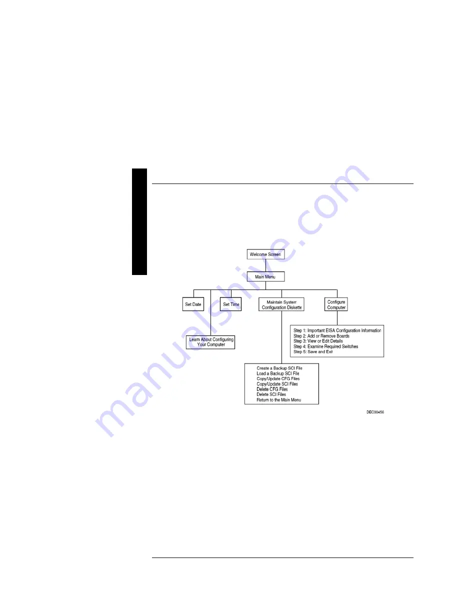
The SCU enables to setup and configure the server using the menu driven items shown in figure 2-1.
Depending on the installed hardware and level of server security required, you might have to access one  or
more of these items to properly configure the server.

Figure 2 - 1  SCU Main Menu Options

Before Using the

SCU

When familiar with utility programs and their uses, refer to the appropriate sections in this chapter to setup or
update the server’s configuration.  Otherwise, carefully read and understand this chapter before attempting to
modify the server’s configuration settings.
Read any README files contained on the System Configuration Utility diskette for additional information.

In addition, have the following items readily available:

♦ 

A 1.44 MB formatted diskette.

♦ 

Configuration (CFG) files supplied with any installed EISA/PCI expansion boards.


Refer to the section, "SCI Files and CFG  Files”, later in this chapter for  more information about CFG
files.

♦ 

Kit installation instructions for any installed optional hardware.

Summary of Contents for Prioris HX590 DP

Page 1: ...S H X Service Maintenance Manual PRIORIS HX590 HX590 DP Server K MN SD00000 02 JG00 A Copyright Digital Equipment Corporation All rights reserved November 1995 NIJMEGEN THE NETHERLANDS MCS LOGISTICS...

Page 2: ...Use duplication or disclosure by the U S Government is subject to restrictions as set forth in subparagraph c 1 ii of the Rights in Technical Data and Computer Software clause at DFARS252 227 7013 Co...

Page 3: ...XE 15 CONFIGURING THE SERVER 15 The SCU 16 Before Using the SCU 16 SCI Files and CFG Files 17 Using the SCU 17 Configure The Computer 18 Adding ISA Boards 19 SCU AND SETUP OPTIONS 19 SCU Main Menu 20...

Page 4: ...he Optional Power Supply 46 Replacing Secondary Cache Memory 47 Replacing a Device Into the Hot Swap Drive Bay 48 SBB LED Status Indicators 49 Replacing the Server Battery Real Time Clock RTC 50 CONNE...

Page 5: ...ss Map 69 PCI Configuration Space Address Map 69 Server Interrupt Levels 69 CHAPTER 6 PASS FAIL CRITERIA 71 APPENDIX A SERVICE NOTES 73 RECOMMENDED TOOLS 73 Other Needed Materials 73 Required Special...

Page 6: ...38 Figure 3 8 Removing the CD ROM drive 39 Figure 3 9 Removing the CPU module 40 Figure 3 10 Replacing the CPU Chip 41 Figure 3 11 Set the CPU Voltage to 3 3 Volt 42 Figure 3 12 Removing the Memory M...

Page 7: ...ument may not apply to the computer s you are servicing since many of the diagnostic tests are designed to test more than one product CAUTION Digital recommends that only A certified engineers attempt...

Page 8: ......

Page 9: ...riteback cache 64 bit memory card supporting up to 512 MB parity or 256 MB ECC memory On board Cirrus 5482 16 bit 512KB video memory 6 PCI slots 3 Primary and 3 secondary and 6 EISA I O slots 10 exter...

Page 10: ...ernel Systems contain no SCSI controller and must be ordered with at least 16MB of DRAM memory With these systems either wide or narrow non RAID or RAID host controllers can be added Kernel systems ma...

Page 11: ...ory Cache FDD HDD Host Contr CD ROM FR 881WW AA 32 MB parity 512KB 1 44MB None Adaptec 2940W 1 channel Wide SCSI 2 600 KB sec FR 881WW AB 32 MB ECC 512KB 1 44MB 4 x 1GB SCSI 2 1 channel Narrow RAID EI...

Page 12: ......

Page 13: ...mory ROM chip The BIOS initializes hardware and boots the operating system when the server is turned on The BIOS also provides access to other services such as keyboard and disk drive The server comes...

Page 14: ...py the above files to it 4 Insert a blank formatted diskette into drive A 5 From drive C type MAKECRD This copies the files to drive A 6 Remove the crisis recovery diskette from drive A and store it i...

Page 15: ...he diskette copy the new file to the upgrade directory and type PHLASH filename 5 Press Enter to continue If not press Esc to cancel Once Enter is pressed PHLASH EXE automatically updates the server s...

Page 16: ...rams and their uses refer to the appropriate sections in this chapter to setup or update the server s configuration Otherwise carefully read and understand this chapterbefore attempting to modify the...

Page 17: ...nstall any optional hardware for example disk drives EISA expansion boards and so on Refer to Chapter 3 Service Procedures 2 Make a backup copy of the supplied System Configuration Utility diskette St...

Page 18: ...tep 1 Important EISA Configuration Information This menu item provides basic EISA configuration information and how it differs from ISA configuration These screens are available at any time during the...

Page 19: ...elect Step 5 Save and Exit to save the configuration and exit the SCU Turn off the server and install the ISA boards CAUTION Do not attempt to physically install boards while the server is turned on S...

Page 20: ...el of required server security you might need to access one or more of the menu items to properly configure the server When accessing the SCU a welcome screen appears followed by the main menu options...

Page 21: ...server boots Extended memory Not user selectable Displays the amount of extended memory each time the server boots Boot Options Menu Fields Settings Comments Boot option A then C C then A C only Each...

Page 22: ...o repeat a keystroke Memory and Cache Options Menu Fields Settings Comments Internal cache Enabled Disabled Enables or disables the server s internal cache External cache Enable Disable Enables or dis...

Page 23: ...r disabled User password is Not user selectable Tells whether or not the user s password is enabled or disabled Set supervisor password Press Enter Enables to set a supervisor password Set user passwo...

Page 24: ...s or disables onboard serial port 1 at the specified address Serial port 2 Auto Disabled 3F8 IRQ4 2F8 IRQ3 3E8 IRQ4 2E8 IRQ3 Enables or disables onboard serial port 2 at the specified address Diskette...

Page 25: ...ween writes PCI burst write Enabled Disabled Enables or disables PCI memory burst write cycles PCI arbiter System default Pure rotating EISA slots PCI slots 4 6 CPU PCI slot 1 PCI slot 2 PCI slot 3 Se...

Page 26: ......

Page 27: ...s properly connected Keep circuit boards and components away from non conductors Keep clothing away from circuit boards and components Keep circuit boards in anti static bags Be cautious when AC power...

Page 28: ...gent should be an all purpose cleaner that is used in house Required Special Tools None Remedial Diagnostic Test Software QAPLUS fe PC Advanced Diagnostic Software latest version Supplier information...

Page 29: ...onnected to server 2 Turn server off 3 Unplug power cord from wall outlet 4 Disconnect power cord and monitor cord from server WARNING You might injure yourself or damage the server if you attempt to...

Page 30: ...CPU module E Main logic board F Memory module G 3 inch diskette drive H Front access 5 inch half height drive bays I CD ROM drive bay J Integral hot swap device bay slots 0 through 6 from top to bott...

Page 31: ...Right Side Legend Component A Power supply B Redundant power supply area C Storage backplane D Contact switch E Ac power plug F Monitor plug G SCSI knockouts back panel H Keyboard and mouse ports I S...

Page 32: ...documentation for server memory address and IRQ requirements Compare that information to the server memory and IRQ requirements in the appropriate CPU module specifications booklet If conflicts are de...

Page 33: ...any electronic component unless you are safely grounded Wear a grounded wrist wrap or touch an exposed metal part of the server s chassis Main Logic Board Jumper Settings Entries in Italic bold in th...

Page 34: ...rocedures Digital PRIORIS HX590 HX590 DP Server 34 MCS Logistics Engineering Nijmegen P R I O R I S H X Main Logic Board Jumper Locations J28 J41 1 2 3 J38 J17 J9 J39 J42 Figure 3 5 Main Board Jumper...

Page 35: ...d Parity memory and ECC memory cannot be mixed together Only 32 MB 2 x 16MB IBM ECC and 64 MB 2 x 32 MB IBM ECC densities are available for ECC memory modules Memory Configurations Bank 0 1 Bank 2 3 B...

Page 36: ...128 MB 2 x 4 MB 2 x 32 MB 2 x 32 MB 136 MB 2 x 4 MB 2 x 64 MB 136 MB 2 x 8 MB 2 x 32 MB 2 x 32 MB 144 MB 2 x 8 MB 2 x 64 MB 144 MB 2 x 4 MB 2 x 4 MB 2 x 4 MB 2 x 64 MB 152 MB 2 x 16 MB 2 x 32 MB 2 x 3...

Page 37: ...HX590 HX590 DP Server Service Procedures MCS Logistics Engineering Nijmegen 37 P R I O R I S H X PRIORIS HX590 HX 590 DP SIMM Locations Bank 7 Bank 6 Bank 5 Bank 4 Bank 3 Bank 2 Bank 1 Bank 0 Figure 3...

Page 38: ...the 3 inch Diskette Drive To remove the 3 inch diskette drive 1 Turn off the computer 2 Disconnect external devices ac power and monitor power 3 Unlock and remove side panels 4 Disconnect power and ri...

Page 39: ...M Drive To remove the CD ROM drive 1 Turn off the computer 2 Disconnect external devices ac power and monitor power 3 Unlock and remove side panels 4 Disconnect power and ribbon cables 5 Remove screws...

Page 40: ...rnal devices ac power and monitor power 3 Unlock and remove left side panel 4 Remove CPU module retaining bracket 5 Carefully remove CPU module from main logic board 6 Replace CPU module and retaining...

Page 41: ...module 2 Place the CPU module on an anti static surface 3 Lift up on the release lever for the ZIF socket 4 Remove the CPU from the ZIP socket pulling it straight up 5 Install the new CPU and return...

Page 42: ...setting Set the CPU voltage to 3 3V 1 Remove the 5V Jumper Module form the 5V connector J100 on the CPU Module 2 Push the 3 3 V Jumper Module on the pins of 3 3V connector J101 on the CPU Module Make...

Page 43: ...and monitor power 3 Unlock and remove left side panel 4 Remove memory module retaining bracket 5 Carefully remove memory module from main logic board 6 Install a higher performance memory module or a...

Page 44: ...X Removing the Main Logic Board To remove the main logic board 1 Turn off the computer 2 Disconnect external devices ac power and monitor power 3 Unlock and remove side panels 4 Remove all connectors...

Page 45: ...rn off the server 2 Disconnect external devices ac power and monitor power 3 Unlock and remove left side panel 4 Remove metal shield 5 Remove screws securing power supply to rear of chassis 6 Release...

Page 46: ...rn off the server 2 Disconnect external devices ac power and monitor power 3 Unlock and remove left side panel 4 Remove metal shield 5 Remove screws securing power supply to rear of chassis 6 Release...

Page 47: ...module 2 Place the CPU module on an anti static surface 3 Locate the secondary cache memory socket on the CPU module and remove the currently installed cache memory module CAUTION Static electricity...

Page 48: ...to the next section SBB LED Status Indicators NOTE Not all SCSI host adapters support the hot swap method Refer to the SCSI host adapter documentation to determine if the hot swap method is supported...

Page 49: ...s active CAUTION For non RAID servers removing a SBB when the left LED is on or flashing can cause the loss or corruption of data For RAID servers the right LED amber is the SBB fault LED and indicate...

Page 50: ...uration settings using the SCU 2 Turn off the server 3 Disconnect external devices ac power and monitor power 4 Unlock and remove left side panel 5 Remove old battery 6 Install new battery Make sure p...

Page 51: ...you connect to the server The server configuration SCSI adapter s and all SCSIdevices must work together for optimum performance When installing SCSI devices use the following guidelines to configure...

Page 52: ...ble Note that The SCSI ID addressing is independent of the single or dual SCSI bus arrangement Make sure to select unique SCSI IDs for all SCSI devices on the SCSI bus You must use a wide SCSI host ad...

Page 53: ...across the SCSI host adapters When arranging SCSI devices make sure each device connected to a SCSI host adapter is assigned a unique SCSI address Each operating system has different limitations rega...

Page 54: ...apter ID7 channel A host termination B 68 pin to 50 pin adapter cable to CD ROM C 68 pin to 50 pin adapter cable to top right drive bay D Backplane 68 pin connector E Terminator F Jumper cable NOTE Th...

Page 55: ...3 If necessary connect appropriate power cable to device 4 Replace and lock side panels 5 Connect external devices and restore power Dual Channel SCSI Bus Legend Legend Component A SCSI host adapter I...

Page 56: ...nal SCSI bus 1 Remove the terminator from the storage backplane for the bus you want to connect 2 Connect the 68 pin unshielded cable connector to the storage backplane A 3 Using a screwdriver gently...

Page 57: ...ives are spun down completely and then turn it back on If the POST detects an error refer to this chapter and take the appropriate steps to correct the problem After the problem has been resolved rest...

Page 58: ...ent SIMM BIOS server battery etc BeepCode Error 2 2 3 BIOS ROM checksum 3 1 1 Test DRAM refresh 3 1 3 Test keyboard controller 3 4 1 Test 512K base address lines 3 4 3 Test 512K base memory 2 1 2 3 Ch...

Page 59: ...ntify diskette drive A and or B Invalid NVRAM media type NVRAM access failed Run the SCU and restore all settings to original values If the problem persists replace the defective component Keyboard co...

Page 60: ...CU and ensure that all settings are correct Save the configuration even when no changes are made If the problem persists replace the defective component System RAM failed at offset nnnn System RAM fai...

Page 61: ...or cable is incorrectly installed Video controller has failed Incorrect VGA drivers installed Adjust the brightness and contrast controls Check all monitor connections Replace the failed component Ins...

Page 62: ...ect the keyboard No response to mouse commands Mouse is password protected Mouse driver not installed Enter the keyboard and mouse password Install the appropriate mouse driver Server operates correct...

Page 63: ...rive Operating system software is not installed on the SCSI boot hard disk drive Requested partition does not exist SCSI boot hard disk drive at wrong SCSI address Format the SCSI hard disk drive Prop...

Page 64: ...eration Refer to Main Logic Board Jumpers Adjust the monitor brightness and contrast controls No monitor display while loading Windows video drivers Monitor type incorrectly set Set the correct monito...

Page 65: ...QAPlus FE Error Messages Component Messages Solution CPU Arithmetic Function Failed General Functions Failed Exception Interrupt in Protected Mode Refresh Failure Logic Functions Failed Reset CPU Repl...

Page 66: ...topped Invalid Date RTC Interrupt Failed Run Setup Replace battery clock CMOS CMOS Clock Test Failed Change time from Setup menu in QAPLUS Serial port COM port failed Serial Chip Error Serial Compare...

Page 67: ...network expansion boards require a specific memory location If that location is already allocated a memory conflict results and the expansion board will not operate as expected Note that some memory I...

Page 68: ...d by BIOS Setup during POST 48 KB EC000 to EFFFF SCSI BIOS if enabled 16 KB F0000 to FFFFF System BIOS memory 64 KB CPU I O Address Map Range hexadecimal Function 0000 to 0CF7 PCI I O space 0CF8 Confi...

Page 69: ...o 3BE LPT3 if enabled 3F0 to 3F7 Diskette controller if enabled 3F8 to 3FF COM1 if enabled PCI Configuration Space Address Map Range hexadecimal Function C0xx CPU bridge C1xx PCI PCI bridge PCI slots...

Page 70: ......

Page 71: ...d Destructive Test Sequential write random read Destructive Test Floppy Disk All Tests Keyboard All Tests COM Ports All Tests LPT Ports All Tests Pointer device All Tests 3 Successful bootstrap of the...

Page 72: ......

Page 73: ...c wrist strap Other Needed Materials Cleaning agent should be an all purpose cleaner that is used in house Required Special Tools None Remedial Diagnostic Test Software QAPLUS fe PC Advanced Diagnosti...

Page 74: ...R I S H X ECO FCO Information BIOS version information Refer to the Digital DECpc Bulletin Board Support for the latest information on BIOS upgrades Network locations North America South America Austr...

Page 75: ...e Spares Catalogue EK A0836 RG Sevice Maintenance Manual Spares Catalogue EK A0815 SV On Line Bulletin Boards The most current product information and technical support is also available on line The m...

Page 76: ......

Page 77: ...e will do our best to make this document a valuable support to your service effort for Digital Please fill out the reader feedback form and send or fax it to Digital Equipment Parts Center b v Att MCS...

Page 78: ......

Page 79: ...Personal Notes...

Page 80: ...Personal Notes...

Page 81: ...Personal Notes...

Page 82: ...Personal Notes...

Page 83: ...on this form are used at Digital s direction Did you find errors in this manual If so specify by page What is your general reaction to this manual format completeness organisation etc Is the document...

Reviews: