


5: Service Procedures
5-122
Manual: Colorwriter LSR 2000 Service Guide
Draft:
Last Modified: January 20, 1996 7:30 pm
File: Service-electrical
Page: 5-122
Colorwriter LSR 2000 Printer
Service Guide
3. Secure the eight mounting screws that attach the
video controller PCB to the bracket.
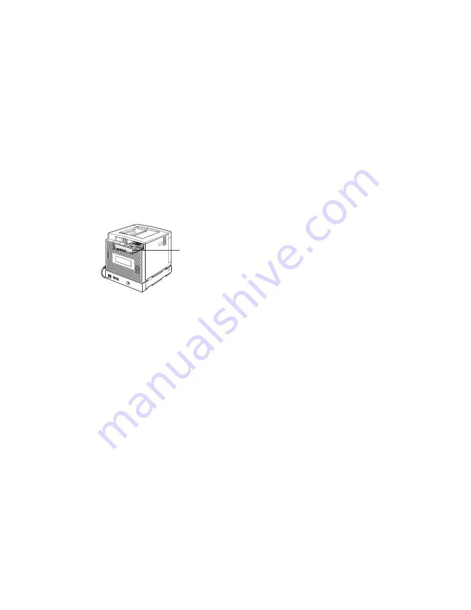
4. Insert the video controller PCB into the slot on the
back of the printer and tighten the panel fasteners
(see the following figure).
Make sure the interface connector on the edge of the
board is securely seated in the connector on the
printer.
Replacing the HDD on the video controller PCB
Factory-installed HDDs (hard disk drives) are thoroughly
tested and burned in before shipment. Hard disk drives
are formatted and loaded with all XJE software.
Additionally, the hard disk drive is used to store spooled
print jobs. Available space on the hard disk drive is
displayed on the Control Panel.
To remove the HDD
1. Turn OFF the printer.
Use ESD precautions when handling internal printer
components.
2. Remove the video controller PCB from the printer
(see “To remove the video controller PCB” on
page 5-120).
Video
controller
5: Service Procedures
Colorwriter LSR 2000 Printer
Service Guide
5-123
Manual: Colorwriter LSR 2000 Service Guide
Draft:
Last Modified: January 20, 1996 7:30 pm
File: Service-electrical
Page: 5-123
3. Remove the SCSI ribbon cable that connects the HDD
to the video controller J5 connector.
4. On the bottom of the video controller bracket,
remove the four screws that secure the HDD to the
video controller PCB.
5. Place the HDD in a antistatic bag.
Do not touch the drive with magnetic objects (such as
magnetic screwdrivers) and avoid placing items such as
credit cards an employee ID cards that are sensitive to
magnets near the HDD.


