Installation and Handling Instructions
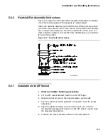
Figure D–3
SIMM Installation
MR-6411-AI
D.4
Cache Installation Instructions
The AXPpci 33 cache is made up of 11 static random access memory
(SRAM) devices.
1
Observe antistatic handling precautions.
2
Two sizes of cache SRAMs are supported on the AXPpci 33. If
installed, SRAMs of the same size and speed must be installed in
all 11 sockets. See Section 2.2.3.2 for information on supported cache
sizes. All SRAMs should be purchased from the same vendor and have
the same data access time.
3
To prevent damage, only handle SRAMs at the edges. Ensure that the
SRAM pins are straight and in line before installation.
4
To install:
a.
Hold the SRAM with the notch or pin 1 designator facing the key
in the socket.
Note: The cache sockets are designed to accept either 28-pin or
32-pin devices, depending on the physical size of the SRAM.
These cache devices must have the power and ground pins
arranged in the evolutionary configuration, that is, on the
corner pins.
b.
Align the SRAM pins over the socket holes ensuring that the
SRAM is oriented correctly.
c.
To avoid bending or distorting the pins, evenly and firmly push the
SRAM into the socket.
d.
Check the SRAMs to be sure each pin is in the correct socket hole
and aligned.
e.
Repeat steps a–d until all 11 SRAMs are installed.
D–5
Summary of Contents for AXPpci 33
Page 10: ......
Page 14: ......
Page 18: ...System Summary Figure 1 1 Main Logic Board MR 6391 AI 1 4...
Page 22: ...Physical Description Figure 2 2 MLB Mechanical Drawing MR 6414 AI 2 4...
Page 23: ...Physical Description Figure 2 3 MLB Component Outline Drawing MR 6401 AI 2 5...
Page 46: ......
Page 64: ......
Page 70: ......
Page 98: ......


