background image

1

System Summary

This chapter presents the physical, performance, and operating
characteristics of the Digital AXPpci 33 motherboard.

Table 1–1 includes features of the DECchip 21066 processor used for
the Digital AXPpci 33. Features are common across all versions of the
motherboard unless specifically differentiated.

Table 1–1

Digital AXPpci 33 System Summary

Software

Operating systems

Microsoft Windows NT, Digital UNIX

System Characteristics

CPU and clock speed

DECchip 21066 RISC microprocessor at 166 MHz (6 ns)
DECchip 21066A RISC microprocessor at 233 MHz (4.3 ns)
DECchip 21068 RISC microprocessor at 66 MHz (15 ns)
DECchip 21068A RISC microprocessor at 100 MHz (10 ns)

Processor upgradeable

ZIF socket for DECchip 21066 processor upgrades

Instruction issue

Up to two instructions issued per clock cycle

Word size

64 bits

Address size

Physical address: 34 bits

Virtual address:

43 bits

Floating-point format

VAX (F and G) and IEEE

Memory (RAM)

Minimum
Maximum
Recommended minimums

8 MB ECC protected
256 MB ECC protected
Windows NT: 16 MB
Digital UNIX: 32 MB

Memory (ROM)

512 KB flash ROM

External cache

Configurable for 0, 256 KB, or 1 MB
(64 data bits and 8 ECC protection bits; 20 ns or 15 ns access)

Memory bus width

64 data bits and 8 ECC bits

Memory bus speed (peak)

80 MB/s

Graphics

Integral graphics

None included.

Graphics options

See Appendix C for a list of tested options.

1–1

Summary of Contents for AXPpci 33

Page 1: ...ide supplies reference configuration and installation information for the Digital AXPpci 33 Alpha PC motherboard Revision Update Information This manual supersedes the Digital AXPpci 33 Alpha PC Mothe...

Page 2: ...uation to assist in preparing future documentation The following are trademarks of Digital Equipment Corporation Alpha AXP AXP DEC DECchip and the DIGITAL logo The following are third party trademarks...

Page 3: ...0 LED Display Connector J6 2 11 2 2 2 11 Mouse Connector PS 2 Compatible J40 2 13 2 2 2 12 Parallel Port Connector J36 2 14 2 2 2 13 PCI Slot Connectors J25 J27 2 14 2 2 2 14 SCSI IDE Busy LED Connect...

Page 4: ...233 MHz Cooling Requirements 3 4 3 1 2 3 DECchip 21068 66 MHz Cooling Requirements 3 5 3 1 2 4 DECchip 21068A 100 MHz Cooling Requirements 3 6 3 1 2 5 Custom Heatsink Design 3 8 3 2 DC POWER INPUTS 3...

Page 5: ...tructions D 2 D 2 6 Heatsink Fan Assembly Instructions D 3 D 2 7 Installation into ZIF Socket D 3 D 3 SIMM INSTALLATION AND REMOVAL INSTRUCTIONS D 4 D 4 CACHE INSTALLATION INSTRUCTIONS D 5 APPENDIX E...

Page 6: ...E 3 7 1 Syntax E 8 E 3 7 2 Options E 9 E 3 7 3 Examples E 9 E 3 8 deposit Command E 10 E 3 8 1 Syntax E 10 E 3 8 2 Options E 10 E 3 8 3 Examples E 11 E 3 9 ISA Configuration Utility isacfg E 11 E 3 9...

Page 7: ...5 Keylock and Power LED Circuit 2 11 2 6 LED Display Circuit 2 12 2 7 SCSI IDE Busy LED Circuit 2 15 2 8 Speaker Circuit 2 19 2 9 Cache Socket 2 20 2 10 SROM Select Jumper Positions J28 and J29 2 23...

Page 8: ...A Grant Jumper J16 2 22 2 25 SROM Select Jumpers J28 and J29 2 22 2 26 SCSI Terminator Jumper J13 2 23 2 27 SIMM Options 2 25 2 28 Variable Lengths of ISA Options 2 26 2 29 Variable Lengths of PCI Opt...

Page 9: ...s B 1 C 1 Tested Options C 1 E 1 SRM Console Conventions E 4 E 2 SRM Console Special Characters E 4 E 3 boot Command Options E 5 E 4 boot Command Examples E 6 E 5 set Command Options E 6 E 6 set Comma...

Page 10: ......

Page 11: ...n appendixes Chapter 1 Provides overall system characteristics Chapter 2 Describes dimensions connectors mounting and configurable features of the module and connectors Chapter 3 Supplies required env...

Page 12: ...value default integer string Horizontal ellipsis points indicate that the preceding item can be repeated one or more times These are used in syntax descriptions and function definitions Horizontal ell...

Page 13: ...C N0627 72 DECchip 21066 and DECchip 21068 Alpha AXP Microprocessor Hardware Reference Manual EC N2681 72 Third Party Documents Contact these organizations for the latest revisions of the documents PC...

Page 14: ......

Page 15: ...microprocessor at 66 MHz 15 ns DECchip 21068A RISC microprocessor at 100 MHz 10 ns Processor upgradeable ZIF socket for DECchip 21066 processor upgrades Instruction issue Up to two instructions issue...

Page 16: ...l SCSI connector seven devices plus a controller Asynchronous operation at 5 MB s or synchronous operation at 10 MB s See Appendix C for a list of tested options IDE One IDE interface supporting up to...

Page 17: ...mance Metrics Alpha Processor Clock Frequency Cache Context Switch Time1 Preemption Time1 Intertask Message Latency1 Semaphore Shuffle Time1 DECchip 21066 166 MHz 1 MB 15 ns 22 6 52 97 116 17 239 74 D...

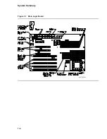
Page 18: ...System Summary Figure 1 1 Main Logic Board MR 6391 AI 1 4...

Page 19: ...required for external serial ports parallel ports and a SCSI port Use the core module assembly dimensions to size the overall module assembly for a specific enclosure 2 2 Main Logic Board The MLB cont...

Page 20: ...on side 1 2 2 1 Physical Mounting The AXPpci 33 MLB is a standard Baby AT form factor with the addition of three 0 157 inch diameter B holes The B holes are module tooling holes used during manufactur...

Page 21: ...erical order Figure 2 3 identifies connector locations and pin orientations for the MLB 2 2 2 1 DC Power Input Connectors J33 and J34 The MLB has two power input connectors J33 and J34 The main power...

Page 22: ...Physical Description Figure 2 2 MLB Mechanical Drawing MR 6414 AI 2 4...

Page 23: ...Physical Description Figure 2 3 MLB Component Outline Drawing MR 6401 AI 2 5...

Page 24: ...dc power connector J34 Table 2 2 DC Power Connector 3 3 V Pin Out J34 Pin Number Function 1 Ground 2 Ground 3 Ground 4 PCI 3 3 V 5 PCI 3 3 V 6 PCI 3 3 V 7 PCI 3 3 V 8 PCI 3 3 V 9 PCI 3 3 V 10 Ground...

Page 25: ...isk Connector J12 The AXPpci 33 supports one floppy disk controller interface J12 This is a 34 position 2 x 17 male shrouded keyed connector Table 2 4 lists the pin numbers and functions for the flopp...

Page 26: ...er Function 1 Ground 2 Halt Reset Normally open Figure 2 4 shows the Halt Reset switch circuit Figure 2 4 Halt Reset Switch Circuit MR 6413 AI 2 2 2 6 IDE Disk Connector J18 The AXPpci 33 supports one...

Page 27: ...4 for further details about ISA option modules The ISA option in slot 1 J24 occupies the same bulkhead that the PCI option in slot 3 J25 occupies making the slots mutually exclusive For definition of...

Page 28: ...LED Connector J9 The keylock and power LED J9 is a 5 position 1 x 5 connector that serves two purposes Pins 1 and 3 provide 5 V and ground for an optional LED indicating dc power is present Pins 4 an...

Page 29: ...gnostic firmware The LEDs show the results of writes to the lowest 8 bits of any address in the range 0 3880 0000 through 0 38ff ffff For consistency it is recommended that address 0 3880 0000 be used...

Page 30: ...n Pin Number Function 1 5 V 2 LED 7 3 No connection 4 LED 6 5 No connection 6 LED 5 7 LED ENABLE L 8 LED 4 9 LEDCLK 10 LED 3 11 No connection 12 LED 2 13 No connection 14 LED 1 15 Ground 16 LED 0 Figu...

Page 31: ...ge 1010 0000 0 KB cache No cache found 1010 0001 256 KB cache 256 KB cache found 1010 0010 1 MB cache 1 MB found 0010 0000 Run time Machine check 1 All unused codes are reserved 2 2 2 11 Mouse Connect...

Page 32: ...23 Ground 11 Busy 24 Ground 12 PE 25 Ground 13 Select 26 No pin installed 2 2 2 13 PCI Slot Connectors J25 J27 The AXPpci 33 supports three PCI option slots 5 V 32 bit Connector J34 connects 3 3 V to...

Page 33: ...J19 The AXPpci 33 supports one SCSI 2 bus using the NCR 53C810 SCSI controller chip The internal SCSI is a 50 position 2 x 25 male shrouded keyed connector CAUTION SCSI terminator power TERM POWER is...

Page 34: ...2 16 Serial Ports COM1 J35 and COM2 J37 Each serial port has a 10 position 2 x 5 connector J35 and J37 If required you can add an adapter cable from these serial port connectors to an appropriate use...

Page 35: ...a and ECC bits within that SIMM Both members of the pair must be the same size and type Bank 0 comprised of J2 and J3 is closest to the DECchip 21066 CPU Bank 1 comprised of J4 and J5 is farthest from...

Page 36: ...3 RAS 69 No connection 34 RAS 70 No connection 35 Data 71 No connection 36 Data 72 Ground 2 2 2 18 Speaker Connector J10 The speaker uses a 4 position 1 x 4 connector J10 The drive circuit is designed...

Page 37: ...256 KB or 1 MB of cache using either 11 32K x 8 or 11 128K x 8 SRAM devices On power up the CPU automatically determines the cache size Cache devices are socketed to allow easy installation by the sys...

Page 38: ...e post 2 2 4 1 Cache Speed Select J17 J17 is a 2 position 1 x 2 header The processor is informed of what speed cache memories are installed through this jumper as outlined in Table 2 19 Table 2 19 Cac...

Page 39: ...Jumper J8 The Halt Reset select jumper J8 is a 3 position 1 x 3 header that determines if the system halts or resets when the Halt Reset switch see connector J11 is closed if installed This jumper ma...

Page 40: ...Pin 1 2 Pin 2 3 2 2 4 5 SROM Select Jumpers J28 and J29 Use these two sets of 6 position 2 x 3 headers J28 and J29 to define console action on power up or reset You must only install one jumper to sel...

Page 41: ...CSI 2 termination SCSI termination is not a software configurable feature Table 2 26 lists the SCSI terminator jumper Table 2 26 SCSI Terminator Jumper J13 Terminator Enabled1 Terminator Disabled Jump...

Page 42: ...he operating system used For Windows NT 16 MB For Digital UNIX 32 MB Figure 2 12 shows a SIMM outline Note that chip placement is for example only Actual quantity and placement of chips vary by SIMM s...

Page 43: ...0 inches EBPXM AC 1 350 inches 4 250 inches EBPXM AD 1 350 inches 4 250 inches EBPXM AE AF 1 900 inches 4 550 inches 2 4 ISA Option Modules Figure 2 13 shows a typical ISA option module it is for refe...

Page 44: ...cessor heatsink 2 5 PCI Option Modules Figure 2 14 shows a typical PCI option module and is for reference only Note that the PCB is fastened to the opposite edge of the bulkhead bracket than an ISA op...

Page 45: ...Notes 1 7 000 inches 1 2 13 415 inches 2 3 13 415 inches 2 Notes 1 Maximum length is limited by the SIMM in J2 2 The maximum length of 13 415 inches is accomplished by adding an extender This allows a...

Page 46: ......

Page 47: ...mperatures below their maximum rating A guideline for maximum case temperatures excluding the DECchip 21066 is 75 C 167 F for metal oxide semiconductor MOS devices and 100 C 212 F for bipolar devices...

Page 48: ...ments using a low profile heatsink high profile heatsink and fan heatsink respectively Table 3 2 DECchip 21066 166 MHz Cooling Using Low Profile Heatsink Air Velocity LFM AXPpci 33 CPU Power Tc Max Th...

Page 49: ...s further thermal analysis by the system integrator This ensures that maximum operating temperatures are not exceeded for any other device including storage devices power supplies PCI or ISA option mo...

Page 50: ...maximum operating temperatures are not exceeded for any other device including storage devices power supplies PCI or ISA option modules or other chips on the MLB Table 3 6 DECchip 21066A 233 MHz Cool...

Page 51: ...irements using a low profile heatsink high profile heatsink and fan heatsink respectively Table 3 8 DECchip 21068 66 MHz Cooling Using Low Profile Heatsink Air Velocity LFM AXPpci 33 CPU Power Tc Max...

Page 52: ...g temperatures are not exceeded for any other device including storage devices power supplies PCI or ISA option modules or other chips on the MLB Table 3 10 DECchip 21068 66 MHz Cooling Using Fan Heat...

Page 53: ...torage devices power supplies PCI or ISA option modules or other chips on the MLB Table 3 12 DECchip 21068A 100 MHz Cooling Using High Profile Heatsink Air Velocity LFM AXPpci 33 CPU Power Tc Max Thet...

Page 54: ...1066 Tambient Tc Power Interface Thermal Resistance Heatsink Thermal Resistance where the variables have these meanings Tc Maximum device case temperatures based on processor type For DECchip 21068 66...

Page 55: ...r Table 3 14 System DC Power Requirements Using 21066 at 166 MHz Nominal Input Typical Load Current Maximum Load Current Required Regulation 5 V 8 5 A 11 A 5 12 V 25 mA 5 12 V 23 mA 10 Table 3 15 Syst...

Page 56: ...comes up and goes down in a defined state On power up the AXPpci 33 power supply asserts the POWER GOOD signal 100 500 ms after the dc power is within the operating range On power down the power suppl...

Page 57: ...elecommunication regulatory standards and met these requirements Formal certification is the responsibility of the system integrator 3 5 Electromagnetic Compatibility Considerations The AXPpci 33 boar...

Page 58: ...t listed such as the power supply and PCI or ISA options are explicitly excluded from these calculations Table 3 20 MTBF Data for the AXPpci 33 MLB Alpha Processor Cache Memory MTBF at 25 C Hours MTBF...

Page 59: ...m Keyboard Interface Alpha Processor Digital Part Number Notes MLB Windows NT ARC N A AT style N A EBP10 AA 1 N A PS 2 style N A EBP10 BA 1 N A PS 2 style N A EBP10 CA 1 MLB and Processor Windows NT A...

Page 60: ...xWorks Run Time License PS 2 style DECchip 21066A 233 EBP22 CW 2 3 4 MLB Processor and Enclosure Windows NT ARC Windows NT AT style DECchip 21066A 233 ETN22 AA 2 3 4 Windows NT PS 2 style DECchip 2106...

Page 61: ...6A 233 ETN42 CX 2 3 4 Notes 1 This configuration does not include the DECchip 21066 processor cache or RAM 2 This DECchip 21066 processor configuration uses the high profile heatsink 3 No preconfigure...

Page 62: ...d Machine Tool Design Freemont N H USA 03044 Telephone 603 642 3601 12 35739 22 Heatsink with fan mounting holes 1 United Machine Tool Design Freemont N H USA 03044 Telephone 603 642 3601 12 35739 34...

Page 63: ...64 MB 70 ns 1 2 Digital EBPXM AE SIMM 256 MB 4 x 64 MB 70 ns 1 2 Digital EBPXM AF Cache 32K x 8 15 ns 28 pin DIP 11 Cypress CY 7C199 15PC 11 Micron MT5C2568 15 11 Motorola MCM6206DP15 11 UMC UM61256A...

Page 64: ......

Page 65: ...py disk interface connector DUPONT 66506 353 J13 SCSI terminator enable jumper AMP 531220 3 J14 SCSI IDE Busy LED connector DUPONT 68000 104 J15 IDE DMA Request select jumper AMP 531220 3 J16 IDE DMA...

Page 66: ...2 connector DUPONT 65611 110 J36 Parallel port interface connector AMP 1 103186 3 J38 PS 2 keyboard port connector HON HAI PRECS MH11067 H1 J39 AT keyboard port connector PREH ELEKTRO 71222 152 J40 PS...

Page 67: ...ch HH 2 0 GB SCSI HD RZ28 PCXAR AK Yes Yes Conner Peripherals CFA1080A IDE No Yes Mass Storage CD ROM Internal low cost double speed SCSI RRD43 PCXCR AD Yes Yes Internal full feature double speed SCSI...

Page 68: ...ISA 1 MB 10 x 7 x 256 No Yes ISA 9 GXE ISA 1280 x 1024 PB2GA CA No Yes Communications ISA Ethernet TP BNC AUI DE202 AB No Yes ISA Ethernet TP BNC AUI DE204 AB Yes Yes ISA Ethernet TP BNC AUI DE205 AB...

Page 69: ...weden PCXAL FF Yes Yes French PCXAL FP Yes Yes German PCXAL FG Yes Yes Italian PCXAL FI Yes Yes North American PCXAL FA Yes Yes Norwegian PCXAL FN Yes Yes Portuguese PCXAL FV Yes Yes Russian PCXAL QT...

Page 70: ......

Page 71: ...ents of the DECchip 21066 D 2 1 Heatsink Labeling No specific heatsink labeling is recommended However if labeling is required it should be done before heatsink assembly to the Alpha processor You may...

Page 72: ...removal is necessary Completely remove the Grafoil thermal pad Clean the stud and mounting plate area of the heatsink surface with Isopropyl alcohol Replace with the new Grafoil and nuts D 2 5 Heatsi...

Page 73: ...ll the heatsink onto the DECchip 21066 before you install the fan onto the heatsink Figure D 2 Fan Heatsink Assembly MR 6403 AI D 2 7 Installation into ZIF Socket 1 Observe antistatic handling precaut...

Page 74: ...banks 0 and 1 can be of different sizes 3 To prevent damage only handle SIMMs at the edges 4 The first pair of SIMMs can be installed in either bank 0 or 1 5 To install a Hold the SIMM at an angle wit...

Page 75: ...ndle SRAMs at the edges Ensure that the SRAM pins are straight and in line before installation 4 To install a Hold the SRAM with the notch or pin 1 designator facing the key in the socket Note The cac...

Page 76: ...action tool is recommended If you use a small flat blade screwdriver to pry out the SRAM chips take care not to damage the SRAM bodies pins or the sockets b Temporarily place SRAMs on antistatic mater...

Page 77: ...indows NT operating system This console uses a menu interface Example E 1 shows a typical console menu displayed when an AXPpci 33 system with Windows NT is powered on Example E 1 Typical Windows NT C...

Page 78: ...M distribution to perform this function E 2 3 3 Menu Option Set Up the System Use the Setup menu to install new firmware list the available devices and modify the system ROM Example E 3 shows a sample...

Page 79: ...nge a boot selection Check boot selections Delete a boot selection Dump boot selections Rearrange boot selections Setup menu Use the arrow keys to select then press Enter E 2 3 3 1 Menu Option Display...

Page 80: ...racters and their functions Table E 2 SRM Console Special Characters Character Key s Function Return Terminates command line input Backspace Deletes the previously typed character Ctrl A Toggles inser...

Page 81: ...he set boot_file command to set an environment variable that specifies a default boot file flags longword longword Additional information for the operating system For Digital UNIX systems valid values...

Page 82: ...command sets or modifies the value of an environment variable Environment variables pass configuration information between the console and the operating system E 3 4 1 Syntax Here is the syntax of the...

Page 83: ...line arguments E 3 5 1 Syntax Here is the syntax of the show command show config device hwrpb memory pal version envar E 3 5 2 Options Table E 7 describes the show command options Table E 7 show Comm...

Page 84: ...t Halt is the default bootdef_dev Sets shows the default device or device list from which the system will attempt to boot If the system software is preloaded the variable is preset to point to the dev...

Page 85: ...s the number of consecutive locations to examine s step Specifies the address increment as a hexadecimal value This option allows you to override the increment that is normally derived from the data s...

Page 86: ...ntax of the deposit command broken across multiple lines for display purposes deposit b w l q o h physical virtual gpr fpr ipr n count s step device address data E 3 8 2 Options Table E 12 describes t...

Page 87: ...referenced by an examine or deposit command The location last referenced by an examine or deposit command The location addressed by the last location referenced by an examine or deposit command data T...

Page 88: ...or multiport adapter this specifies the device on the adapter all Shows the entire configuration table Overrides all other commands init Returns the configuration to the default condition mk Adds an...

Page 89: ...RQ 14 and ISA DMA channel 3 are allocated for the option The name WIDGET109 is bound to the driver isacfg slot 1 This command will display the entire configuration information for all devices configur...

Page 90: ...nfiguration It adds the first instance of a DE204 or DE205 Ethernet card to the configuration table The card is configured at slot 1 device 0 I O base address 300 memory base d0000 memory length 10000...

Page 91: ...st firmware console Two forms of the utility are available one that can be used from the ARC console and another that can be booted from the SRM console F 2 How to Obtain the Latest Firmware The lates...

Page 92: ...more than one drive connected highlight the drive you want to contain the partition and press the ENTER key Take care to select the correct drive the arcinst exe utility does not use the same drive na...

Page 93: ...ard 70 ns 36 bit SIMMs 32 or 33 bit SIMMs will not work What build devices are available for Windows NT At this time the only available build device for Windows NT is a SCSI CD ROM drive The ARC conso...

Page 94: ...es the default assignments Table G 1 IRQ Defaults IRQ Use 00 Counter timer 01 Keyboard 02 Unavailable 03 COM 2 04 COM 1 05 ISA PCI 06 Floppy 07 Parallel printer 08 Unavailable 09 ISA PCI 10 ISA PCI 11...

Page 95: ...ing Check all cables including a check for Proper termination of the SCSI cable Proper cabling of the CD ROM drives Proper cabling of the floppy disk cable There are two ways to key a floppy cable bot...

Page 96: ...s A Digital UNIX disk must be a SCSI disk What are the available interrupt DMA and address spaces The following applies to ISA interrupts DMA channels and I O address space 16 ISA interrupts 0 15 Inte...

Page 97: ...hat happens during system startup During system startup 1 The system loads an initial bootstrap from SROM which transfers control to the flash ROM 2 The flash ROM contains the SRM console for Digital...

Page 98: ......

Reviews: