Physical Description
2.2.2.3
Fan Connector (J1)
The fan connector (J1) is intended to power the DECchip 21066 processor’s
specified heatsink fan, or an enclosure mounted fan, not to exceed
250 mA. J1 is a 3-position vertical male-keyed connector.
CAUTION: Exceeding 250 mA may damage the MLB.
Table 2–3 lists the pin numbers and functions for the fan connector.
Table 2–3
Fan Connector Pin-Out (J1)
Pin Number
Function
1
+12 V
2
No connection
3
Ground
2.2.2.4
Floppy Disk Connector (J12)
The AXPpci 33 supports one floppy disk controller interface (J12). This is
a 34-position (2 x 17) male-shrouded keyed connector.
Table 2–4 lists the pin numbers and functions for the floppy disk
connector.
Table 2–4
Floppy Disk Connector Pin-Out (J12)
Pin
Number
Function
Pin
Number
Function
1
Ground
2
DENSEL
3
Ground
4
MTR3 L
5
Ground
6
DRATE0
7
Ground
8
INDEX L
9
Ground
10
MTR0 L
11
Ground
12
DR1 L
13
Ground
14
DR0 L
15
Ground
16
MTR1 L
17
No connection
18
DIR L
19
Ground
20
STEP L
21
Ground
22
WRDATA L
23
Ground
24
WGATE L
25
Ground
26
TRK0 L
27
No connection
28
WP L
29
Ground
30
RDDATA L
31
Ground
32
HDSEL L
33
Ground
34
DISKCH L
2–7
Summary of Contents for AXPpci 33
Page 10: ......
Page 14: ......
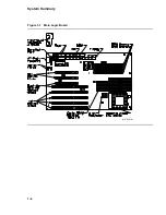
Page 18: ...System Summary Figure 1 1 Main Logic Board MR 6391 AI 1 4...
Page 22: ...Physical Description Figure 2 2 MLB Mechanical Drawing MR 6414 AI 2 4...
Page 23: ...Physical Description Figure 2 3 MLB Component Outline Drawing MR 6401 AI 2 5...
Page 46: ......
Page 64: ......
Page 70: ......
Page 98: ......


