Physical Description
2.2.2.12
Parallel Port Connector (J36)
This is a parallel port 26-position (2 x 13) connector (J36). You can add an
adapter cable from this MLB connector to an appropriate user connector, if
required. You can interface the pin-out of this connector to a 25-position D
connector using insulation displacement connectors (IDCs) on both ends.
Table 2–13 lists the pin numbers and functions of the parallel port
connector.
Table 2–13
Parallel Port Connector Pin-Out (J36)
Pin
Number
Function
Pin
Number
Function
1
STROBE L
14
AUTOFD L
2
Data 0
15
ERROR L
3
Data 1
16
INIT L
4
Data 2
17
SLCTIN L
5
Data 3
18
Ground
6
Data 4
19
Ground
7
Data 5
20
Ground
8
Data 6
21
Ground
9
Data 7
22
Ground
10
ACK
23
Ground
11
Busy
24
Ground
12
PE
25
Ground
13
Select
26
No pin installed
2.2.2.13
PCI Slot Connectors (J25–J27)
The AXPpci 33 supports three PCI option slots (5 V/32 bit). Connector
J34 connects 3.3 V to 3.3 V capable PCI cards. One slot supports a short
PCI module; two support long PCI modules. The PCI option components
in PCI slot 3 (J25) occupy the same space the ISA option in ISA slot 1
(J24) would occupy, making the slots mutually exclusive. For definitions
of the signal and power pin assignments, see the document PCI Local Bus
Specifications referred to in the Preface. For further information about
PCI option modules, see Section 2.5.
2.2.2.14
SCSI/IDE Busy LED Connector (J14)
The 4-position (1 x 4) J14 connector provides the BUSY L signal to drive a
LED that indicates bus traffic on either the SCSI bus or IDE bus.
Table 2–14 lists the pin numbers and functions of the SCSI/IDE Busy LED
connector.
2–14
Summary of Contents for AXPpci 33
Page 10: ......
Page 14: ......
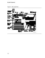
Page 18: ...System Summary Figure 1 1 Main Logic Board MR 6391 AI 1 4...
Page 22: ...Physical Description Figure 2 2 MLB Mechanical Drawing MR 6414 AI 2 4...
Page 23: ...Physical Description Figure 2 3 MLB Component Outline Drawing MR 6401 AI 2 5...
Page 46: ......
Page 64: ......
Page 70: ......
Page 98: ......


