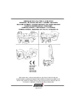
Operating Manual
BG-180EC
General
4
3.4 Operating
elements
Handgrip and Operating lever
Fig. 3.2
Before Switching on the BG-180EC, the front part of the
grindingmachine must be lifted by pushing the handgrip (1) down to
floor level till the machine is approximately 10cm from the ground.
3.5 Electric
components
The Switch box is equipped with all control elements and instruments
to monitor the grinding machine.
Fig. 3.3
1 Electrical inlet power supply 3
Stop button
5
Terminal safety switch
2 Electrical inlet motor
4
Start button
Summary of Contents for BG-180EC
Page 1: ...Operating Manual BG 180EC ...
Page 2: ......
Page 4: ......
Page 8: ...Operation Manual BG 180EC Technical Data 4 1 5 Machine type designation ...
Page 40: ...Operating Manual BG 180EC Operation 6 Notes ...
Page 60: ...Operating Manual BG 180EC Electrics 4 8 3 Electric circuits diagram of E01532 110V 28 0A 50Hz ...
Page 70: ...Operating Manual BG 180EC Fault diagnosis 4 Notes ...
Page 71: ...BG 180EC Operating Manual Spare Parts 1 Contents Chapter 10 10 1 Spares Parts List BG 180EC ...
Page 74: ...Operating Manual BG 180EC Spare Parts 4 Fig 10 2 ...


