ENGLISH
32
e. Fixed table top
f.
Traverse
rails
g. Leg
h1. Left fence (small)
h2. Right fence (large)
i.
Dust
shroud
j. Mitre latch lever
k. Mitre clamp lever
l. Height adjustment crank
m. Radial arm
n. End-cap
o. Cable
p. Dust outlet
q. Yoke assembly
r.
Motor
s1. Left table strip
s2. Right table strip
t1. Left table extension
t2. Right table extension
u. Bevel scale
v. Roller head assembly
w. No-volt release switch
x. Electronic control box
INTENDED USE
The radial arm saw has been designed for professional woodworking.
This high precision machine can be easily and quickly set to crosscut,
bevel, mitre. For optimum safety, all major controls have both a latch
and a locking device. Also refer to the quick reference chart at the end
of the section. This saw is designed for use with a 300 mm diameter
carbide tip blade.
DO NOT
use under wet conditions or in presence of flammable liquids
or gases.
The radial arm saw is a professional power tool.
DO NOT
let children come into contact with the tool. Supervision is
required when inexperienced operators use this tool.
Electrical Safety
The electric motor has been designed for one voltage only. Always
check that the power supply corresponds to the voltage on the rating
plate.
If the supply cord is damaged, it must be replaced by a specially
prepared cord available through the D
E
WALT service organization.
Mains Plug Replacement
(U.K. & Ireland Only)
SINGLE-PHASE ONLY
If a new mains plug needs to be fitted:
• Safely dispose of the old plug.
• Connect the brown lead to the live terminal in the new plug.
• Connect the blue lead to the neutral terminal.
• Connect the green/yellow lead to the earth terminal.
WARNING:
Follow the fitting instructions supplied with
good quality plugs. Recommended fuse: 13 A.
WARNING:
This product must be earthed. Always check
that the power supply corresponds to the voltage on the
rating plate.
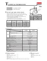
Contact a qualified electrician if a new CEE 16 A industrial plug needs
to be fitted.
Using an Extension Cable
An extension cord should not be used unless absolutely necessary.
Use an approved extension cable suitable for the power input of your
machine (see technical data). The minimum conductor size is 1 mm
2
;
the maximum length is 30 m.
SINGLE-PHASE MACHINES
Use an approved 3-core extension cable suitable for the power input
of this machine (see technical data). The minimum conductor size is
1.5 mm².
THREE-PHASE MACHINES
Please ensure the cable is provided with CEE 16A industrial plug/
coupler according to IEC 60309.
When using a cable reel, always unwind the cable completely.
Voltage Drops
Inrush currents cause short-time voltage drops. Under unfavourable
power supply conditions, other equipment may be affected.
If the system impedance of the power supply is lower than 0.25 Ω,
disturbances are unlikely to occur.
Sockets used for these machines shall be fused with 16 Amperes
cut-out with an inert characteristic.
ASSEMBLY AND ADJUSTMENT
WARNING:
To reduce the risk of injury, turn unit off
and disconnect machine from power source
before
installing and removing accessories, before adjusting or
changing set-ups or when making repairs. Be sure the
switch is in the OFF position. An accidental start-up can
cause injury.
WARNING:
For optimum performance of your saw, it is of
vital importance to follow the procedures in the paragraphs
below.
Set Up
MOUNTING THE HEIGHT ADJUSTMENT CRANK (FIG. 1, 2)
1. Apply the height adjustment crank (l) with the cross head screw.
NOTE:
Automatic return arm may need to be moved to allow
height adjustment.
2. Raise the height adjustment crank high enough to provide
clearance for removal of various elements under the motor.
ASSEMBLING THE LEGSTAND (FIG. 1, 3, 4)
The legstand components and fasteners are packed separately.
1. Remove all parts from the package.
2. Lock the arm using the mitre clamp lever (k).
3. Tilt the machine carefully from the pallet until the rear of the column
is resting on the floor.
4. Place a piece of wood (y) under the edge of the table (fig.3).
5. Assemble the legs (g) as shown using the nuts, bolts and flat
washers provided.
NOTE:
Do not tighten.
6. Mount the traverse rails (f) (fig. 4).
7. Firmly tighten all fasteners.
8. Tilt the assembly to upright position.
WARNING:
The machine must be level and stable at all
times.
IMPORTANT:
Assistance may be required to lower and raise
assembly.
MOUNTING THE AUTOMATIC RETURN (FIG. 1, 5–10)
1. The automatic return comes partially assembled as shown in
figure 5.
2. Partially unscrew automatic return retaining screw (z) with 6 mm
hex key to allow for rotation of automatic return system (fig. 6).
3. Unlock and move the head (fig. 7).
4. Rotate the automatic return. Insert the second screw (aa).
NOTE:
Do not tighten (fig. 8).
5. Set the automatic return, checking correct alignment with the roller
head (v) (fig. 1, 9).
Summary of Contents for DW721KN
Page 1: ...www eu DW721KN DW722KN ...
Page 3: ...1 Figure 1 m n a b e o t1 g h1 s1 i j k l c a b r v p w p u h2 i q d f x s2 t2 ...
Page 4: ...2 Figure 4 Figure 3 Figure 2 g g y f l Figure 7 Figure 5 Figure 6 y z z ...
Page 5: ...3 e dd Figure 12 e t Figure 9 Figure 8 aa Figure 11 Figure 10 Figure 13 bb cc ...
Page 6: ...4 Figure 14 Figure 15 Figure 17 Figure 18 Figure 19 Figure 16 s1 ee ...
Page 7: ...5 Figure 21 Figure 22 ii gg ff hh Figure 23 x Figure 20 w Figure 24 Figure 25 d kk jj m l ...
Page 8: ...6 Figure 26 mm ll Figure 27 Figure 28 pp oo nn nn ...
Page 9: ...7 Figure 29 Figure 30 Figure 31 Figure 33 Figure 32 qq e Figure 34 oo nn nn ...
Page 10: ...8 Figure 36 Figure 39 Figure 38 Figure 37 rr ss uu k j v v Figure 40 rr Figure 35 tt v v ...
Page 12: ...10 Figure 48 Figure 47 Figure 50 Figure 49 Figure 51 Figure 52 a5 a4 a3 u a5 a6 a6 ...
Page 13: ...11 DW721KN DW722KN ...
Page 127: ...125 ...


