


DDFP
Page 10
SECTION 2
ELECTRONIC SPEED SWITCH
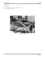
The speed switch is located on the rear or back side of the
instrument panel.
There are two (2) functions built into the speed switch. First
to terminate starter cranking, once the engine is running.
Second to signal the controller and ef fect an engine shut-
down in the event of an engine overspeed condition.
Features of the speed switch are a "manual reset b utton" on
the face of the switch, which must be pushed into reset the
switch should the engine shutdo wn from an overspeed con-
dition. Additionally, a varification circuit to assist in check-
ing or setting the overspeed set point.
CALIBRATION
Both crank terminate (SW#1) and o verspeed (SW#2) set
points, are set at the factory and should not require addition-
al calibration. Adjustments can be made to the set points of
SW#1 and/or SW#2 if required using a je welers screw dri-
ver. Turning the corresponding adjustment scre w CW to
increase or CCW to decrease the set point. To access either
adjustment screw remove the small co ver plate on the f ace
of the speed switch.
Crank terminate (SW#1) adjustment should be done reading
"engine crankshaft" speed at the front of the engine using a
hand held tachometer . For starter protection and optimum
engine stability , this switch should be calibrated to 1000
RPM.
Overspeed (SW#2) adjustment should be done r eading "en-
gine crankshaft" speed at the front of the engine using a
hand held tachometer . This switch should be calibrated to
120% of rated speed, but ne ver higher than 3200 RPM.
Refer to the stainless steel nameplate located at the right rear
of the engine for the correct rated speed.
OVERSPEED VARIFICATION
To varify the function of the overspeed signal (SW#2) with-
out overspeeding the engine, install a jumper wire on termi-
nals "C & D" of the speed switch. This will provide the con-
troller with an o verspeed signal and engine shutdo wn at
67% of calibrated RPM.
Start the engine via the controller , the speed switch will
effect an overspeed signal and shutdown protecting both the
engine and pump.
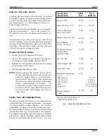
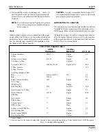
EXAMPLE
Rated Speed : 2100 RPM
Overspeed Shutdown : 2520 RPM (120% of 2100 RPM)
Varification Shutdown : 1688 RPM (67% of 2520 RPM)
CAUTION
After v arification of SW#2 the jumper wir
e must be
removed and the "reset b utton" pushed in to re-instate nor-
mal operation of the engine and speed switch.


