SECTION 3.4
DDFP
Page 27
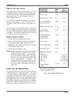
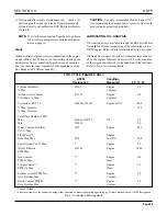
Max.
PPM
Boron (B)
Nitrite (NO2)
Nitrates (NO3)
Silicon (Si)
Phosphorous (P)
pH
1000
800
1000
50
300
8.5
Min.
PPM
1500
2400
2000
250
500
10.5
To properly check inhibitor concentrations it may be neces-
sary to contact your local DDC Distributor/Dealer for assis-
tance. Refer to P arts Information Section 6, Page 45, to
obtain the DDC part number for the F
actory Coolant
Analysis Kit. This kit can be purchased for nominal fee for
analyzing the condition of the engine's coolant.
PROCEDURE FOR FILLING ENGINE
During filling of the cooling system, air pockets may form.
The system must be pur ged of air prior to being put in ser-
vice. This is best accomplished by f illing with a pre-mix
solution, to the top of f iller neck. Install the pressure cap,
start and run engine until the temperature staabilizes at
approximately 170° - 190° F (77° - 91° C). During this
warming process, you may
see coolant coming from the o verflow tube attached at the
pressure cap location. This is a normal condition since the
coolant expands as it heats up. When the o verflow ceases,
stop the engine.
NOTE:
Air entrapment in I-53 engines is v ery lik ely to
occur due to cooling system design. Upon initial
fill with a pre-mix solution. It is recommended that
the coolant be allowed to stand for a four hour peri-
od prior to starting.
To verify that the coolant is at a safe operating level, it's best
to wait until the engine temperature drops to approximately
120°F (49°C), or lower, before removing the pressure cap.
After the cap is removed, the level should be within 2 inch-
es (51mm) of the filler neck.
NOTE:
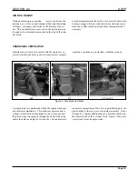
I-71 engines have incorporated the use of a coolant
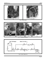
recovery bottle (white plastic bottle) Fig
4
. During
initial filling of the cooling system, it will be nec-
essary to f ill the Reco very Bottle to the Cold Full
line with the pre-mix solution. Start and run the
engine as indicated abo ve. After reaching normal
operating temperature check the coolant le vel in
the recovery bottle to v erify that the le vel is at the
Hot Full line, if not add coolant to the bottle.
Following the same instructions as abo ve, wait for
the engine coolant temperature to drop before
removing the pressure cap.
The coolant le vel
should be at the pre viously mention height. The
coolant level must remain between Hot and Cold
run lines on the recovery bottle.
CAUTION:
Do not remove pressure cap while coolant is at
normal operating temperatures. Possible per-
sonal injury could result from the expulsion of
hot coolant.
PRESSURE CAP
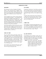
Like most cooling systems, the Heat Exchanger type oper-
ates under pressure. A typical cap shown in Fig.
5
maintains
system pressure to raise the coolant boiling point and per-
mits a some what higher operating temperature without
coolant loss. Pressure cap values can vary in different engine
series. Refer to Section 5 for your engine type.
All pressure caps include a vacuum valve which opens dur-
ing cool down. This prevents an internal vacuum from being
formed which could contrib ute to leaking seals and hoses
collapsing.
NOTE:
I-71 engines use a coolant reco very bottle. The
pressure cap includes a rubber ring-type seat.
When the cap installed this ring forms a positi ve
seal between the filler neck and cap. During engine
cool down, if the wrong type cap is used, coolant
cannot transfer back into the heat e xchanger from
the recovery bottle. This can progress into an over-
heated engine and possible damage.
Fig. 5 - Typical Coolant Cap
Fig. 3 - Proper Concentrations Of Inhibitors
Fig. 4 - Coolant Recovery Bottle

