DDFP
SECTION 3.1
Page 14
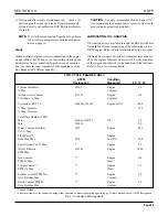
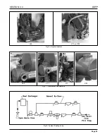
FUEL SYSTEM SCHEMATICS
Fig. 1 - DDFP Fuel System
1. Fuel Strainer (Primary)
2. Fuel Transfer Pump
3. Fuel Filter (Secondary)
4. Check Valves
5. Cylinder Head with Internal Manifolds
6. Fuel Injectors
7. Fuel Pipes (Inlet and Return to Injector)
8. Restricted Fuel Fitting
9. Return to Tank
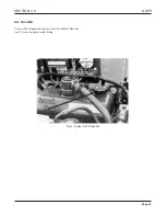
ENGINE MECHANICAL GOVERNOR
A v ariable speed mechanical go vernor pro vides speed
control of the engine. The certified engine speed, shown on
FM/UL/ULC label, has been preset at the f actory. Minor
speed adjustments can be made in the f ield to meet specific
installation condition, generally ± 50 RPM maximum.
The go vernor is controlled by the R UN-STOP solenoid.
This solenoid is activated by a signal from the AEC. A man-
ual over-ride switch on the instrument panel, placed in the
MANUAL
position, allows manual operation should the
AEC malfunction.
Note:
Always leave the instrument panel switch in the
AUTO
position when the unit is unattended.


