DDFP
SECTION 3.3
LUBRICATION SYSTEM
OPERATION
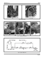
The lubricating oil system is schematically illustrated in
Figures 1, 2 and 3 for the Inline and VEE engines. The sys-
tem consists of an oil pump, oil cooler, a full-flow oil filter,
by-pass valves at the oil cooler and filter, and pressure regu-
lator valves at the pump and in the c ylinder block main oil
gallery. Positive lubrication is ensured at all times by this
system.
Oil for lubricating the connecting rod bearings, piston pins,
and for cooling the piston head,
is pro vided through the
drilled hole in the crankshaft from the adjacent forw
ard
main bearings. The gear train is lubricated by the o verflow
of the oil from the camshaft pock et through a connecting
passage into the flywheel housing from the camshaft, bal-
ance shaft, and idler gear bearings. The blower drive gear
bearing is lubricated through an e xternal pipe from the rear
horizontal oil passage of the cylinder block.
On the Inline engines the oil from the cam pocket enters the
blower and overflows through two holes, one at each end of
the blo wer housing, providing lubrication for the blo wer
drive gears at the rear end and for the go vernor mechanism
at the front. On the VEE engines, the blower drive gear is
lubricated from the rear of the blower.
OIL COOLER
All engines use a plate type oil cooler. Between each engine
model, the major difference lies in the number of plates in
each cooler. The number of plates required is determined by
engine horsepo wer de veloped. All the oil cooler systems
incorporate oil bypass valves in the event of plate core plug-
ging.
It should be understood that improper engine maintenance
could adversely effect the ef ficiency of the oil cooler sys-
tem. Please refer to the technical data Section 5, for specif-
ic lube oil temperature and engine coolant temperature
ranges for each engine model.
LUBE OIL FILL
On I-71 engines, the oil fill is located on the right rear . On
the VEE engines, it is found in the right bank v alve rocker
cover. On the 53 Series engine, the oil fill is also located on
the rocker cover. See technical data, Section 5 for oil v ol-
umes and specif ications on each engine model. A typical
oil fill location is shown in Figure 5
,
Page 24.
OIL LEVEL DIPSTICK
On most DDFP engines, the dipstick is located on the lower
left side. Exceptions are the I-71 and 12V92 models where
the dipstick is located on the right. Oil level can be checked
only when the engine is at rest (not running). Oil levels must
be maintained between the low and full marks.
NOTE:
Due to the basic engine design, DDC engines
retain large volumes of oil in the block while
running. For this reason, proper oil level cannot
be checked immediately after engine shut of f.
Wait approximately 10 minutes before check-
ing oil le vel. Do not add oil to a running
engine; overfilling can occur!
LUBE OIL PUMP
The positive displacement gear type pump is mounted to the
main bearing caps on I-71 and dri ven from the front end of
the crankshaft. On the I-53,V-71 and V-92 engines the pump
is found in the lower front cover and driven by the front end
of the crankshaft. The I-71, V-71 and V-92 have a pressure
relief located on the dischar ge side of the pump,
which
maintains pressure being delivered to the oil filter and cool-
er. The I-53 engine does not use a pressure relief v alve but
does incorporate the use of the f ilter and oil cooler bypass
valve to maintain pressure.
All four engines use an oil pressure regulator valve to main-
tain oil g alley minimum pressures. See technical data
Section 5 for specifics per engine model.
Page 20


