____________________________________________________________________________________
DESMI Pumping Technology A/S
6
Tagholm 1
9400 Nørresundby
–
Denmark
Tel: +45 96 32 81 11 Fax: +45 98 17 54 99
E-mail:
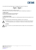
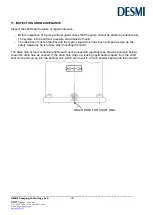
The pump is to be lifted in the following way:
The lifting straps must not bear against sharp edges and corners.
5. DISMANTLING
5.1 ACCESS TO IMPELLER
The numbers in brackets refer to the position numbers on the assembly drawing.
Dismantle guard (69).
ø215/265
Remove Allen screws (77) between coupling part motor (71) and spacer (72) and the screws (76), which
hold the flexible coupling (74) to the coupling part pump (70). It is not necessary to remove the screws
(also 76) which hold the flexible coupling to the spacer. After a vertical pull downwards take out the spacer
(72). Loosen the pointed screw (73) and pull the coupling part pump (70) off the shaft. Dismantle the
copper pipe (58). Remove Allen screws (22) which hold the shaft seal cover (20) to the pump casing.
Remove the shaft seal cover from the pump casing by means of the pointed screws (86). The bearing
housing with shaft and impeller can now be lifted up from the pump as a unit, and the impeller can be
inspected.
ø330/415/465/525
Remove Allen screws (76) at each end of the coupling, and remove the spacer (72). Loosen the pointed
screw (73) and pull the coupling part pump (70) off the shaft. Dismantle the copper pipe (58). Remove set
screws (22) with washers (23) which hold the shaft seal cover to the pump casing. Remove the shaft seal
cover from the pump casing by means of the pointed screws (86) The shaft seal cover and the bearing
housing with shaft and impeller can now be lifted up from the pump as a unit, and the impeller can be
inspected.


