background image

11

201839

OWNER’S MANUAL

Test Pressures Equal To or Less Than
1/2 PSIG (3.5 kPa)

1.

Close equipment shutoff valve (see Fig-
ure 16).

2.

Pressurize supply piping system by either
using compressed air or opening main gas
valve located on or near gas meter.

3.

Check all joints from gas meter to
equipment shutoff valve. Apply mix-
ture of liquid soap and water to gas
joints. Bubbles forming show a leak.

4.

Correct all leaks at once.

Pressure Testing Furnace Gas
Connections

1.

Open equipment shutoff valve (see Fig-
ure 16).

2.

Open main gas valve located on or near
gas meter.

3.

Make sure control knob of furnace is
in the OFF position.

4.

Check all joints from equipment shutoff
valve to gas inlet pipe. Apply mixture
of liquid soap and water to gas joints.
Bubbles forming show a leak.

5.

Correct all leaks at once.

6.

Turn on furnace (see Operating Fur-
nace
, pages 12 and 13). Check the rest
of the internal joints for leaks.

7.

Turn off furnace (see To Turn Off Gas
to Furnace
, page 13).

O

POSI

PO

Off Position

On Position

Figure 16 - Equipment Shutoff Valve

INSTALLATION

(Continued)

CONNECTING TO
ELECTRICAL SUPPLY

IMPORTANT:

 Follow all local codes when

connecting electricity to furnace. In the ab-
sence of local codes, refer to the latest edi-
tion of the National Electrical Code ANS/
NFPA No. 70.
 If you are not familiar with
wiring codes, have a qualified electrician do
the wiring.

It is best to plug furnace into a separate and
permanent electrical line circuit.

1.

Supply a 120-volt, 60-cycle, grounded
outlet at furnace location.

2.

The furnace has a three-pronged
(grounded) plug. Use only a grounded,
three-prong outlet.

IMPORTANT:

 Some local codes require

rigid or semi-rigid conduit or metallic
sheathe cable. When using a semi-rigid or
metallic sheathe cable, the installer must
terminate the supply wire in the terminal
box opening.

Performance Check

Plug furnace into three-pronged outlet. If
ignitor remains on after main burner igni-
tion or if the valve chatters, you may have
reversed polarity.

1.

Unplug furnace.

2.

Turn off electricity to outlet.

3.

Reverse 120-volt connections inside
outlet.

4.

Turn on electricity to outlet.

5.

Plug in furnace. Ignitor should turn off
after main burner ignites. If ignitor does
not turn off, or if valve continues to
chatter, turn off furnace and unplug.
Call a qualified service person.
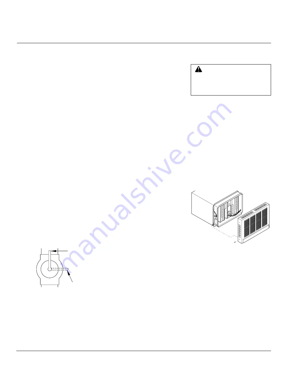
ATTACHING CABINET
FRONT COVER

 CAUTION: Do not operate fur-

nace with front cover removed or
mounted wrong. If front cover is
mounted wrong, you cannot se-
cure it to cabinet with screws.

1.

Hook top of front cover over top cabi-
net flange.

2.

Secure the sides of front cover to lower
sides of furnace cabinet with two
screws provided (see Figure 17).

IMPORTANT:

 You may have removed fur-

nace from furnace cabinet during installa-
tion. You must correctly install furnace
within cabinet. If not, front cover will not
properly attach to cabinet. Make sure gas-
kets for intake and exhaust tubes are in
place. Make sure intake and exhaust tubes
extend into vent caps on cabinet back and
are secured with screws. Make sure you
secured flange on bottom of furnace to flange
on bottom front of cabinet.

Figure 17 - Attaching Front Cover to
Cabinet

Summary of Contents for DYNAVENT DNV25PB

Page 1: ...NING Improperin stallation adjustment alteration service or maintenance can cause injury or property dam age Refertothismanual for correct installation and operational proce dures Forassistanceor addi...

Page 2: ...LP gas is odor less An odor making agent is added to pro pane LP gas The odor helps you detect a propane LPgasleak However theodoradded to propane LP gas can fade Propane LP gas may be present even t...

Page 3: ...For purposes of input adjustment SPECIFICATIONS Install and use furnace with care Follow all localcodes Intheabsenceoflocalcodes use the latest edition of the following National Fuel Gas Code ANS Z223...

Page 4: ...installing thermostat in a wall make sure there are no pipes or wiring in the hollow wallabovethefurnace Thethermostatwires will pass through this wall from the attic Mounting hardware needed to moun...

Page 5: ...000 BTU Hr Model Use a proper sized drill bit Drill holes through wall and into studs at marked locations 40 000 BTU Hr Model Use a proper sized drill bit On wall stud side of opening drill holes thro...

Page 6: ...else that would interfere with install ing thermostat Do not mount thermo stat to stud If there are any obstruc tions choose a new location 3 Provide two 18 gauge insulated stranded wires for the the...

Page 7: ...t Wires to Thermostat Wall Anchors CAUTION Use only new black iron or steel pipe Copper tubing may be acceptable in cer tain areas Check local codes Use pipe large enough in diam eter to allow proper...

Page 8: ...de furnace back into furnace cabi net Make sure exhaust tube gaskets are in place Make sure exhaust and intake vent tubes extend into vent caps on back of cabinet Replace two screws by exhaust vent s...

Page 9: ...0 BTU Hr 15 000 BTU Hr for other gas appliances 55 000 BTU Hr total 55 000 2500 22 Locate 22 or higher on chart below According to the chart below you should use 40 feet or less of 3 8 pipe 125 feet o...

Page 10: ...5 CAUTION Usepipejointseal ant that is resistant to liquid pe troleum LP gas Slab Floor Installation Equipment Shutoff Valve Test Gauge Connection To Gas Supply 3 Min Sediment Trap Gas Piping Entering...

Page 11: ...0 cycle grounded outlet at furnace location 2 The furnace has a three pronged grounded plug Use only a grounded three prong outlet IMPORTANT Some local codes require rigid or semi rigid conduit or met...

Page 12: ...Do not try to light the burner by hand 8 Plug in furnace 9 Set thermostat to desired setting If thermostat is set above room tem perature the blower will come on 10 Allow approximately 45 seconds for...

Page 13: ...forces the combus tion products out of the exhaust tube s The Combustion air blower is sealed so that air does not pass between it and the circulating room air blower 3 When the blower motor reaches...

Page 14: ...r mixture Wipe cabinet and front cover to remove dust Use a vacuum cleaner to remove dust from front cover louvers EXHAUST AND INTAKE VENTS Make sure the exhaust and intake vents are not blocked The i...

Page 15: ...okay check for defective motor 5 Be sure the microswitch is sailing in far enough to open the solenoid valve and to energize the ignition control If the switch is not sailing in clean any dust or dir...

Page 16: ...t it WARNINGS Never connect unit or ignition circuit to 230 volts Never operate unit with glo bar touching burner or any other ground Damage to ignition control will occur Be sure sensor probe never t...

Page 17: ...bar broken 2 A Check for voltage 24 volts A C at valve 40 seconds after glo bar begins to glow If voltage present but valve not opening replace valve B If no voltage at valve check brown wire at igni...

Page 18: ...Be sure probe is positioned in the burner flame and glowing cherry red Check wire and wire connections at probe and ignition control B If wire and wire connections okay check for voltage across brown...

Page 19: ...hite Open WIRING DIAGRAMS Figure 21 Wiring Diagram 40 000 BTU Hr Model Figure 20 Wiring Diagram 25 000 BTU Hr Model Note Use only original replacement parts Thiswillprotectyourwarrantycoveragefor part...

Page 20: ...41 www portableheaterparts com sales portableheaterparts com techservice portableheaterparts com F B D 1349 Adams Street Bowling Green KY 42103 3414 1 800 654 8534 270 846 1199 Fax 1 800 846 0090 fran...

Page 21: ...1244 Operating Instructions Decal English 1 191246 Operating Instructions Decal French 1 531010 Warning Decal 1 191262 Nameplate 1 Parts available not shown You must order nameplate and operating inst...

Page 22: ...8 x 3 8 2 3 191241 Front Cover Trim 1 4 030642 Front Cover Assembly 1 5 100896 Cabinet Assembly 1 6 070511 Cabinet Insulation right and left sides 1 7 120158 Screw 8 x 3 8 2 8 160912 Thermostat inclu...

Page 23: ...44 Terminal Block 1 10 121224 Screw 10 x 3 4 2 11 070487 Gasket 1 12 231143 Transformer Assembly 1 13 121252 Screw 10 x 3 8 6 14 020983 Combustion Chamber Heat Shield Assembly 1 15 070606 Heat Shield...

Page 24: ...Terminals 1 13 070607 Heat Shield Gasket 1 14 020982 Combustion Chamber Heat Shield Assembly 1 15 061663 Wire Clamp 2 16 121252 Screw 10 x 3 8 12 17 230560 Limit Switch 1 KEY PART NO NUMBER DESCRIPTIO...

Page 25: ...3 4 5 6 7 8 9 10 11 12 KEY PART NO NUMBER DESCRIPTION QTY 1 120717 Hex Nut 10 24 2 2 121459 Screw 10 24 x 1 2 2 3 010701 Burner Assembly 1 4 180215 Main Burner Orifice 1 5 121388 Screw 10 x 1 2 4 6 07...

Page 26: ...PART NO NUMBER DESCRIPTION QTY 1 120717 Hex Nut 10 24 4 2 010621 Left Burner Assembly 1 3 010623 Right Burner Assembly 1 4 070591 Manifold Gasket 1 5 171167 Manifold Assembly 1 6 180188 Main Burner Or...

Page 27: ...oom air 1 8 121421 Hex Lock Nut 10 24 3 9 050751 Crossover Tube 1 10 121388 Screw 10 x 1 2 4 11 070385 Crossover Tube Gasket 2 12 121227 Screw 10 24 x 1 2 2 13 070362 Universal Bushing 1 14 231231 Cap...

Page 28: ...ombustion Air Cover Assy 1 12 121388 Screw 10 x 1 2 3 13 070420 Combustion Air Crossover Gasket 1 14 390318 Combustion Air and Motor Cover Assembly 1 KEY PART NO NUMBER DESCRIPTION QTY 15 121227 Screw...

Page 29: ...___________________ _______________________________________________________________________________________________ ____________________________________________________________________________________...

Page 30: ...lity of the owner TO THE FULL EXTENT ALLOWED BY THE LAW OF THE JURISDICTION THAT GOVERNS THE SALE OF THE PRODUCT THIS EXPRESS WARRANTY EXCLUDES ANY AND ALL OTHER EXPRESSED WARRANTIES AND LIMITS THE DU...

Reviews: