background image

Get
ting Star

ted

Connections

Set
up

Pla
ybac

k
Remot

e Contr

ol

Multi-z

one

Inf
or

mation

Tr

oubleshooting

ENGLISH

About the Auto Setup

The Audyssey MultEQ auto setup function detects the presence of 
each speaker and automatically calculates the speaker size, channel 
level,  distance,  and  optimal  crossover  frequency  setting.  Audyssey 
MultEQ corrects acoustical distortions within the listening area.
Before starting, connect and position all of your speakers.
Once  started,  MultEQ  will  play  a  series  of  test  tones  through  each 
speaker.

If an error message appears during the measurements, check “Error 
Messages”,  take  the  advised  action,  then  start  the  measurements 
again (

v

page 23).

a

 Start Menu

The settings found at this stage are applied automatically.

G

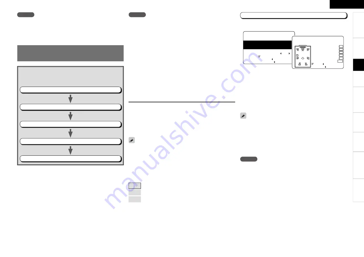
Auto setup fl ow

H

Step 1:


Speaker Detection

Step 2:


Measurement

Step 3:


Calculation

Step 4:


Check

Step 5:


Store

NOTE

• Loud test sounds may be played during Audyssey MultEQ automatic 

speaker setup. This is part of normal operation. If there is background 

noise in room, these test signals will increase in volume.

• Do not stand between the speakers and setup microphone or allow 

obstacles in the path while the measurements are being made. This 

will cause inaccurate readings.

• Make the room as quiet as possible. Background noise can disrupt 

the  room  measurements.  Close  windows,  silence  cell  phones, 

televisions,  radios,  air  conditioners,  fl uorescent  lights,  home 

appliances, light dimmers, or other devices as measurements may 

be affected by these sounds. 

  Cell phones should be placed away from all audio electronics during 

the  measurement  process  as  Radio  Frequency  Interference  (RFI) 

may cause measurement disruptions (even if the cell phone is not in 

use).

• Operating 

MASTER VOLUME

 during the measurements will cancel 

the measurements.

Auto Setup

Optimize settings for speakers in use.

Step 1 : Speaker Detection

NOTE

Do not change the speaker connections or subwoofer volume after 
“Step 1”.

The  speaker  connection  and  polarity  are  detected  at  the  fi rst 
measurement  position  (main  listening  position).  The  following 
attributes are also determined at this time: “Speaker Size”, “Speaker 
Distance”, “Channel Level”, “Crossover Frequency”.

Press 

ui

 to select “Amp Assign”, then press 

ENTER

.

Press 

o


p

 to select “7.1ch”, then press 

ENTER

.

Press 

ui

 to select “Start 

0

”, then press 

o

.

Press 

ui

 to select “Next 

0

”, then press 

o

.

  • To cancel the measurements, press 

o

.

• If  the  result  differs  from  the  actual  connection  status  or  an  error 

message appears, use 

i

 to on-screen display “Retry 

0

” and then 

press 

o

 to repeat the measurement.

• If  the  result  still  differs  from  the  actual  connection  status  after 

re-measurement  or  the  error  message  still  appears,  it  is  possible 
that  the  speakers  are  not  connected  properly.  Turn  the  AVR-2309 
off,  check  the  speaker  connections  and  repeat  the  measurement 
process from the beginning.

Menu screen

 F

r

    1-1.Start Menu

Step1:Speaker Detection

Audyssey MultEQ

at ear height at

        Front Sp.  A

        Amp Assign

        Start

        Cancel

Please place microphone

main listening position.

Next

Retry

Front Sp.

Center Sp.

Subwoofer

Surround Sp.

S.Back Sp.

Auto Setup

Step1:Speaker Detection

Audyssey MultEQ

Yes
Yes
Yes
Yes
Yes

2spkrs

NOTE

• Do  not  disconnect  the  setup  microphone  until  the  auto  setup 

procedure is completed.

• When  using  headphones,  unplug  the  headphones  before  starting 

the auto setup procedure.

n

 Front Speaker

The  front  speaker  to  be  measured  can  be  selected  ahead  of  time 
here.

[Selectable items]

A

 :  Output test tone from front speakers A.

B

 :  Output test tone from front speakers B.

A+B

 :  Output test tone from front speakers A and B.

n

 Amp Assign

Advanced setting : changes power amplifi er assignment.
For details, refer to “Amp Assign” (

v

page 29).

Specifi

 cations

Summary of Contents for AVR-2309

Page 1: ...AV SURROUND RECEIVER AVR 2309 Owner s Manual Bedienungsanleitung Manuel de l Utilisateur Italiano Espa ol Nederlands Svenska Book 2 v English Deutsch Fran ais PRESET CODE Book 1...

Page 2: ...Erkl rung bezieht den folgenden Standards entspricht EN60065 EN55013 EN55020 EN61000 3 2 und EN61000 3 3 Entspricht den Verordnungen der Direktive 2006 95 EC und 2004 108 EC DECLARATION DE CONFORMITE...

Page 3: ...altas temperaturas Permite la suficiente dispersi n del calor cuando est instalado en la consola Vermijd hoge temperaturen Zorg er bij installatie in een audiorack voor dat de door het toestel geprodu...

Page 4: ...nto dell unit osservare le normative o le leggi locali in vigore Non gettare le batterie n incenerirle ma smaltirle conformemente alla normativa locale sui rifiuti chimici Questo prodotto e gli access...

Page 5: ...el 25 g Crossover Frequency 26 h Front Speaker Setup 26 HDMI Setup 26 a Color Space 26 s RGB Range 26 d Auto Lipsync 26 f HDMI Audio Out 26 g HDMI Control 26 h Power Off Control 27 Audio Setup 27 a EX...

Page 6: ...54 Quick Select Function 55 Personal Memory Plus Function 55 Last Function Memory 55 Backup Memory 55 Resetting the Microprocessor 55 Playback Other Operations and Functions Remote Control Unit Operat...

Page 7: ...the Remote Control Unit Getting Started Check that the following parts are supplied with the product q Owner s manual 1 w Getting Started 1 e Service station list 1 r Power cord Cord length Approx 1...

Page 8: ...o and p buttons on the remote control unit The control functions in the same way as the cursor o button when turned counterclockwise as the cursor p button when turned clockwise The control functions...

Page 9: ...this lights when receiving analog stereo broadcasts TUNED This lights when the broadcast is properly tuned in RDS This lights when receiving RDS broadcasts Display Getting Started Q8Master volume indi...

Page 10: ...oDigital audio connectors OPTICAL COAXIAL 12 14 Q0Analog audio connectors AUDIO 13 14 Q1COMPONENT VIDEO connectors 12 13 Q2HDMI connectors 11 12 14 Q3VIDEO S VIDEO connectors 12 14 Q4FM AM antenna ter...

Page 11: ...utton 38 q w r e t y u o Q2 Q1 i Q0 q ZONE2 power buttons 62 w Source select buttons 46 e Video select button V SEL 33 r Tuner system buttons 47 t Test tone button TEST 25 y MAIN ZONE power buttons MA...

Page 12: ...rding to the equipment being connected Preparations NOTE Do not plug in the power cord until all connections have been completed When making connections also refer to the operating instructions of the...

Page 13: ...ype of connector as the video input connector The resolution of the HDMI input compatible monitor connected to the AVR 2309 can be checked at menu Information HDMI Information vpage 45 When viewing HD...

Page 14: ...peaker terminals The protection circuit may be activated if the core wires touch the rear panel or if the and sides touch each other v Protection circuit Never touch the speaker terminals while the po...

Page 15: ...combination of components in some cases the video signals will not be output When connecting using an HDMI DVI converter adapter the video signals may not be output properly due to poor connections w...

Page 16: ...ng instructions The audio signals output from the HDMI connectors are only the HDMI input signals When using an optical cable for the digital audio connection make the settings at menu Input Setup Ass...

Page 17: ...k vpage 35 Use a DENON control dock for iPod ASD 1R ASD 3N or ASD 3W sold separately to connect the iPod to the AVR 2309 For instructions on the control dock for iPod settings refer to the control doc...

Page 18: ...Input Setup Assign Component In vpage 35 NOTE Do not connect the output of the component connected to the AVR 2309 s OPTICAL2 output connector to any input connector other than OPTICAL2 R L R L R L R...

Page 19: ...nna supplied Ground AM outdoor antenna n AM loop antenna assembly Remove the vinyl tie and take out the connection line Bend in the reverse direction a With the antenna on top of any stable surface Mo...

Page 20: ...ay Remote you cannot use the RS 232C connector as an external controller vpage 31 RS 232C connector This connector is used for an external controller b If you wish to control the AVR 2309 from an exte...

Page 21: ...s item press RETURN b Select Default Yes then press o to reset to the default setting 5Press ENTER to enter the setting 6Press MENU or A MENU to nish Operations The same operation is possible on the m...

Page 22: ...place microphone main listening position 3 1 Assign Digital In OPT1 iPod Dock None Assign Digital OPT1 Screen title Submenu title Press o to execute Press op to change the setting Current setting Cur...

Page 23: ...9 31 Amp Assign Volume Control Source Delete On Screen Display Quick Select Name Trigger Out Remote ID Setup 232C Port Display Setup Lock Parameter vpage 38 43 n Surround Parameter Mode Cinema EQ DRC...

Page 24: ...in more effective correction To make manual adjustments to the settings see pages 24 26 About the main listening position M The main listening position refers to the most central position where one w...

Page 25: ...s will cancel the measurements Auto Setup Optimize settings for speakers in use Step 1 Speaker Detection NOTE Do not change the speaker connections or subwoofer volume after Step 1 The speaker connect...

Page 26: ...on or direction of a speaker is altered the Auto Setup should be performed again to ensure the correct EQ solution for the new room configuration F Menu screen F q w Auto Setup Step2 Measurement Audys...

Page 27: ...ETUP MIC jack on the main unit Check the speaker connections too high or Retry Cancel Ambient noise is Level is too low Auto Setup Caution Audyssey MultEQ Too much noise in the room for accurate measu...

Page 28: ...ker setting is other than None sound may not be emitted from the surround back speaker depending on the playback source In this case make a menu Parameter Surround Parameter SB CH Out setting other th...

Page 29: ...on how to select set and cancel settings for each menu see Menu Operations vpage 17 25 When the menu Speaker Configuration Surround Back Speaker setting vpage 24 is set to 1spkr the surround back spea...

Page 30: ...lways set the crossover frequency to 80 Hz When using small speakers however we recommend setting the crossover frequency to a higher frequency 26 HDMI Setup Make settings for HDMI video audio output...

Page 31: ...p s 2ch Direct Stereo Make speaker settings for 2 channel mode playback Setting To change the settings select Custom Selectable items Basic Use the same settings as in Speaker Setup Custom Make separa...

Page 32: ...distorted OFF Do not use compression This is the recommended setting 28 Getting Started Connections Setup Playback Remote Control Multi zone Information Troubleshooting ENGLISH g EQ Preset Set MultEQ...

Page 33: ...2 Setup 5 Option Setup 3 Audio Setup Option Setup Make various other settings a Amp Assign Define how the amplifier for the surround back speaker channels is used The places where the surround back am...

Page 34: ...SOURCE SELECT Text Input source and mode display Selectable items ON Turn display on OFF Turn display off Screensaver Make screensaver settings Use the screensaver to prevent burn in on the monitor s...

Page 35: ...rol ID Selectable items 1 2 3 4 k 232C Port Set when external controller or 2 way remote control unit is connected Selectable items Serial Control Set when using an external controller 2Way Remote Set...

Page 36: ...2 Video 4 Rename 5 Source Level 6 iPod 3 Input Setup VCR Repeat Mode All Shuffle Mode OFF 3 6 iPod Displayed when source name is changed with Rename Input Setup ENTER op INPUT MODE ui uiop INPUT ENTER...

Page 37: ...or the HDMI video output Input sources for which Delete is selected at Source Delete cannot be selected Convert Automatically convert video input signal to monitor output format Input source DVD HDP T...

Page 38: ...ted for input sources for which the menu Assign setting is set to HDMI In or Digital In vpage 35 Only set PCM and DTS when playing the respective signals Operating from the main unit or remote control...

Page 39: ...l playback only the video signals are output to the monitor The audio signals input from the analog digital and EXT IN connectors are not output to the monitor Digital In Select digital input connecto...

Page 40: ...electing the surround mode Select by turning SELECT ENTER or pressing STD Selectable items DOLBY PLgx or DOLBY PLg z The signals are decoded in DOLBY PLgx or DOLBY PLg for playback DTS NEO 6 The signa...

Page 41: ...g upon factors such as the Input signal Whether or not surround back speakers are being used For details see page 69 e Direct Playback Selecting the mode Select by turning SELECT ENTER or pressing D S...

Page 42: ...adjustment Press MENU or A MENU during adjustment Operating from the main unit Use SELECT ENTER to select the surround mode nDuring PCM 2ch Analog DOLBY DIGITAL 2ch DIRECT STEREO DTS NEO 6 7CH STEREO...

Page 43: ...s ON Cinema EQ is used OFF Cinema EQ is not used The Music mode is also effective for movie sources including a lot of stereo music a Mode Select the mode to match the source cinema source music sourc...

Page 44: ...is set to 2spkrs or 1spkr at the menu Manual Setup Speaker Setup Speaker Configuration setting z3 This can be selected when playing DTS sources z4 This can be selected when playing DTS sources includi...

Page 45: ...Turn tone adjustments off Selectable items ON Allow tone adjustment treble bass OFF Playback without tone adjustment The tone cannot be adjusted when in the DIRECT mode A9 Bass Adjust low frequency ra...

Page 46: ...o Setup again or return to the setting after running Auto Setup with Auto Setup Parameter Check Restore Operating from the main unit or remote control unit Press DYNAMIC VOLUME Dynamic EQ Volume ON Gr...

Page 47: ...ight listening Audio Delay Compensate for mismatched timing between video and audio This cannot be adjusted when playing in the EXT IN DIRECT or STEREO mode with Front Speaker set to Large Tone Contro...

Page 48: ...g STATUS The figure is the correction value when the standard level is corrected Items to be checked Surround Mode The currently set surround mode is displayed SIGNAL The input signal type is displaye...

Page 49: ...TATUS is pressed the set s status can be checked on the display 480p Color Space RGB 4 4 4 Pixel Depth 8bits Resolution 5 3 HDMI Signal Info 5 6 Preset Station A1FM 87 50MHz A2FM 89 10MHz A3FM 98 10MH...

Page 50: ...Operations During Playback Adjusting the Master Volume Press MUTING To cancel press MUTING again Muting can also be canceled by adjusting the master volume Plug the headphones into the PHONES jack on...

Page 51: ...equencies continuously The time for which the on screen display are displayed can be set at Manual Setup Option Setup On Screen Display vpage 30 The remote control unit can be used to operate external...

Page 52: ...adcasting service which allows a station to send additional information along with the regular radio program signal The following three types of RDS information can be received with this unit 1Either...

Page 53: ...teps 2 to 3 b If no other TP station is found when all the frequencies have been searched NO PROGRAMME is displayed TP Search Use this function to find RDS stations broadcasting traffic programs TP st...

Page 54: ...ng ENGLISH Specifi cations ENTER p SOURCE SELECT STATUS ui ON STANDBY ENTER CHANNEL 8 9 uip SOURCE CONTROL 1 SOURCE CONTROL 2 iPod OFF 1 2 6 7 uip MODE TUNING ENTER Front Rear Button located on both t...

Page 55: ...yed in browse mode Only alphanumeric characters and certain symbols can be displayed Any characters that cannot be displayed are replaced with period The time for which the on screen display are displ...

Page 56: ...be recorded 4Play the program source For operating instructions refer to the respective equipment s operating instructions To record FM or AM broadcasts select the broadcast vpage 47 5Start recording...

Page 57: ...g If the TV you are using has both connection jacks use the optical digital connection When using these functions set as follows menu Manual Setup HDMI Setup HDMI Control vpage 26 AVR 2309 power off c...

Page 58: ...2309 with equipment compatible with the HDMI control function vpage 53 2Put the power on for all the equipment connected to the HDMI 3Check the settings for all the equipment connected to the HDMI and...

Page 59: ...mic EQ Dynamic Volume Front Speaker settings and volume to the conditions you want to store 2Press and hold the desired QUICK SELECT until Memory appears on the display The current settings will be me...

Page 60: ...and year of manufacture this function cannot be used for some models even if they are of makes listed in the list of preset codes Some manufacturers use more than one type of remote control code Refe...

Page 61: ...rd Tuning down up Manual search fast reverse fast forward Manual search fast reverse fast forward Manual search fast reverse fast forward Manual search fast reverse fast forward 8 9 CH Auto search cue...

Page 62: ...Audio Audio BAND PICTURE ADJUST b1 Top menu AM FM switching Picture adjust Picture adjust ENTER Enter setting Enter setting Enter setting Enter setting Enter setting MEMORY SUBTITLE b1 Favorite memory...

Page 63: ...he component you want to set No CD 1 iPod NETWORK 2 TUNER 3 DVD HDP 4 VCR 5 No setting 0 Punch Through Function Punch Through is a function allowing you to operate 1 2 3 0 6 7 8 and 9 on CD iPod NETWO...

Page 64: ...ections and Operations SBL SBR FL SW C FR SL SR MAIN ZONE 7 1ch Setting 1 F7 1 channel playback 7 1ch Amp Assign mode Speaker terminal Amp Assign mode FRONT CENTER SURROUND SURROUND BACK AMP ASSIGN R...

Page 65: ...R SL FR FL Front B Bi Amp FR FL FL A FR A Bi Amp connection FL B FR B Bi Amp connection The Front A or Front B channel for Bi Amp use is output from the speakers connected to the SURR BACK AMP ASSIGN...

Page 66: ...29 The ZONE2 volume can be adjusted only when ZONE2 is selected at menu Manual Setup Option Setup Amp Assign vpage 29 Turning off the Sound Temporarily q Set SOURCE CONTROL 1 to AUDIO and SOURCE CONTR...

Page 67: ...use them G1H Using surround back speaker s q When mainly playing movies Recommended when your surround speakers are single or 2 way speakers Surround back speakers Subwoofer Surround speakers Monitor...

Page 68: ...discrete digital audio format adding a surround back SB channel to the DTS digital surround sound Decoding of conventional 5 1 channel audio signals is also possible according to the decoder DTS ES M...

Page 69: ...dyssey MultEQ is a registered trademark of Audyssey Laboratories Audyssey Dynamic EQ is a trademark of Audyssey Laboratories Audyssey Dynamic Volume is a trademark of Audyssey Laboratories HDMI High D...

Page 70: ...S S OFF A A A A A A DTS 96 24 S D D D D S OFF S 0dB S ON S S OFF A A A A A A DTS HD S D D D D S OFF S 0dB S ON S S OFF A A A A A A 7CH STEREO S D D D D S OFF S 0dB A S A A A A A A A ROCK ARENA S D D D...

Page 71: ...A S OFF S OFF S OFF A DOLBY TrueHD A A A A A S 0dB A S OFF S OFF S OFF A DTS SURROUND A A A A A S 0dB S OFF S OFF S OFF S OFF A DTS 96 24 A A A A A S 0dB S OFF S OFF S OFF S OFF A DTS HD A A A A A S...

Page 72: ...A A A A A A A A A F A A A A A DOLBY DIGITAL EX z1 z4 A A A A A A A A A A A S S S S A DOLBY D HD EX z1 z4 A A A A A A A A A S S A A A A A DOLBY DIGITAL A A A A A A A A A A A S F F F A DOLBY D D HD PLg...

Page 73: ...S S S S MULTI CH PURE DIRECT A S A A A A A A A A A A A A A A M PURE D PLgx CINEMA z2 z4 A S A A A A A A A A A A A A A A M PURE D PLgx MUSIC z1 z4 A S A A A A A A A A A A A A A A M CH PURE DIRECT 7 1 z...

Page 74: ...rimposed on video signal and output z2 On screen display superimposed on S Video signal and output COMPONENT or HDMI On screen display only displayed for the MENU button on the main unit or the A MENU...

Page 75: ...round mode other than the PURE DIRECT mode 31 38 GGeneralH Symptom Cause Countermeasure Page DOLBY DIGITAL indicator does not appear on display Blu ray Disc player DVD player s digital audio output se...

Page 76: ...ed from center speaker You are playing a monaural source TV AM radio broadcast etc in the STANDARD Dolby DTS Surround mode The mode is set to something other than STANDARD Dolby DTS Surround 37 No sou...

Page 77: ...Set when Manual Setup On Screen Display Tuner Information is not OFF Set when Manual Setup On Screen Display iPod Information is not OFF 9 9 30 30 30 30 GVideoH Symptom Cause Countermeasure Page HDMI...

Page 78: ...dB when video convert set to OFF S Video connectors Input output level and impedance Y brightness signal 1 Vp p 75 ohms C color signal 0 3 PAL 0 286 NTSC Vp p 75 ohms Frequency response 5 Hz 10 MHz 0...

Page 79: ...alora 033 041 Samsung 007 011 051 059 070 083 087 089 113 Sanky 081 Sansui 005 026 029 045 061 085 114 Sanyo 032 033 053 087 091 115 116 SBR 042 Scott 017 020 086 089 093 117 Sears 013 023 028 031 033...

Page 80: ...15 S Samsung 014 023 Scientific Atlanta 004 024 025 Signal 014 SL Marx 014 Starcom 009 Stargate 014 T Teleview 014 Tocom 007 016 TV86 019 U Unika 011 United Artists 006 Universal 010 011 V Viewstar 01...

Page 81: ...Denon Brand Company D M Holdings Inc Printed in China 5411 10091 008D www denon com...

Reviews: