background image

ENGLISH

32

Advanced Operation

Advanced Operation

ENGLISH

Preset memory

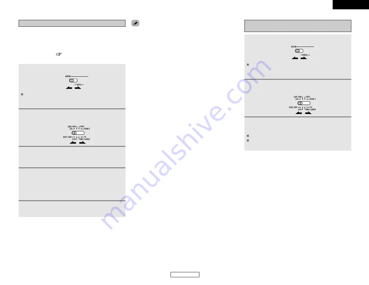
1

Set the 

MODE 1

switch to “AUDIO” or “VIDEO”.

2

Set the 

MODE 2

switch to the component to be

registered.

3

Press the 

ON/SOURCE

and 

OFF

button at the

same time.

• The indicator starts flashing.

• DENON and other makes of components can be operated by

setting the preset memory.

• This remote control unit can be used to operate components of

other manufacturers without using the learning function by
registering the manufacturer of the component as shown in the
list of preset codes (

End of this manual).

• Operation is not possible for some models.

Set to the AUDIO side for the CD, TAPE or CDR/MD position,
and to the VIDEO side for the DVD/VDP, DBS/CABLE, VCR
or TV position.

• The signals for the pressed buttons are emitted while setting

the preset memory. To avoid accidental operation, cover the
remote control unit’s transmitting window while setting the
preset memory.

• Depending on the model and year of manufacture, this function

cannot be used for some models, even if they are of makes
listed in the list of preset codes.

• Some manufacturers use more than one type of remote control

code. Refer to the included list of preset codes to change the
number and verify correct operation.

• The preset memory can be set for one component only among

the following: CDR/MD, DVD/VDP and DBS/CABLE.

2

The preset codes are as follows upon shipment from the
factory and after resetting:
• TV, VCR .........................................HITACHI
• CD, TAPE.......................................DENON
• CDR/MD ........................................DENON (CDR)
• DVD/VDP .......................................DENON (DVD)
• DBS/CABLE...................................ABC (CABLE)

4

Referring to the included list of preset codes,
press the 

NUMBER

buttons to input the preset

code (a 3-digit number) for the manufacturer of
the component whose signals you want to store
in the memory.

5

To store the codes of another component in the
memory, repeat steps 1 to 4.

Operating a component stored in the preset
memory

1

Set the 

MODE 1

switch to “AUDIO” or “VIDEO”.

2

Set the 

MODE 2

switch to the component you

want to operate.

Set to the AUDIO side for the CD, TAPE or CDR/MD position,
and to the VIDEO side for the DVD/VDP, DBS/CABLE, VCR
or TV position.

3

Operate the component.

For details, refer to the component’s operating instructions.
Some models cannot be operated with this remote control
unit.

Summary of Contents for AVR-1506

Page 1: ...AV SURROUND RECEIVER AVR 1506 OPERATING INSTRUCTIONS MODE D EMPLOI...

Page 2: ...bel If you are not sure of the type of power supply to your home consult your product dealer or local power company For products intended to operate from battery power or other sources refer to the op...

Page 3: ...ofer Yes Delay Time Front L 12ft Front R 12ft Center 12ft Surr L 10ft Surr R 10ft S Back L 10ft S Back R 10ft SW 12ft Digital In Assignment SW Mode Norm Cr Over 80Hz Test Tone TEST TONE Yes COAX1 CD C...

Page 4: ...heater sources such as DVD as well as providing outstanding high fidelity reproduction of your favorite music sources As this product is provided we recommend with an immense array of features before...

Page 5: ...or TV away from this unit s power supply cord and input output connection cables Noise or disturbance tends to occur particularly when using indoor antennas or 300 ohm feeder wires We recommend using...

Page 6: ...buttons 29 30 o STANDARD NIGHT button 21 25 0 5CH 7CH STEREO button 26 1 DIRECT STEREO button 20 2 V AUX INPUT terminals 9 3 SURROUND MODE button 18 4 SURROUND PARAMETER button 21 5 SELECT knob 18 21...

Page 7: ...ER button 19 ZONE2 buttons 34 35 MAIN buttons 4 34 The Dolby Surround Pro Logic II x Cinema or Music mode can be chosen directly by pressing the CINEMA or MUSIC button on the remote control unit durin...

Page 8: ...unit check whether there are any faults with the wiring of the speaker cables or input cables and wait for the unit to cool down if it is very hot Improve the ventilation condition around the unit an...

Page 9: ...DEO OUT COMPONENT VIDEO OUT Y PB PR OPTICAL OUT F H G D R L R L A S VIDEO IN VIDEO IN Monitor TV COMPONENT VIDEO IN Y PB PR F H G For best picture quality especially with progressive DVD and other hig...

Page 10: ...monitor TV Turning on the power 6 Set the MODE 1 switch to AUDIO only when operating with the remote control unit 2 MODE 1 INPUT SELECTOR ON SOURCE SURROUND MODE SPEAKER VOLUME ON STANDBY SURROUND MOD...

Page 11: ...ht Note that binding pin plug cables together with power supply cords or placing them near a power transformer will result in hum or other noise Analog terminal Stereo A R L R L Orange Pin plug cable...

Page 12: ...l Connecting a video camera or video game Video camera Video game R L AUDIO OUT VIDEO OUT R L R L A F Connecting the external inputs EXT IN terminals DVD Audio Video Super Audio CD player External dec...

Page 13: ...he above point in mind and make connections according to the equipment s instruction manuals The signals input to the color difference component video terminals are not output from the VIDEO output te...

Page 14: ...emote control unit Connecting a room to room remote control unit NOTE For instructions on installation and operation of separately sold devices refer to the devices operating instructions OUTPUT INPUT...

Page 15: ...select the parameter Front Large Large Small Center Small Large Small None 5 Press the SETUP button to finish system set up Display Setting the Speaker Configuration 1 Press the CURSOR F F or G G but...

Page 16: ...k channel If the subwoofer has sufficient low frequency playback capacity good sound can be achieved even when Small is set for the front center and surround speakers Select Large or Small not accordi...

Page 17: ...of channels set to LARGE are produced from those channels 2 Crossover Frequency When Subwoofer is set to Yes at the Speaker Configuration setting set the frequency Hz below which the bass sound of th...

Page 18: ...urround L channel level manual mode 9 Press the CURSOR F F or G G button to set the surround L channel level then press the CURSOR H H button to switch to the subwoofer channel level manual mode 10Pre...

Page 19: ...e that the surround mode setting is also stored separately for the different input sources q Analog and PCM 2 channel signals STEREO w 2 channel signals in the Dolby Digital DTS or another multi chann...

Page 20: ...o the listening position 14 Front L R Center Surround L R Subwoofer 12 ft 12 ft 10 ft 12 ft Surround Back L R 10 ft 13 14 16 Digital In Assignment This assigns the digital input terminals for the diff...

Page 21: ...TEREO or DSP SIMULATION cannot be selected In play modes other than the external input mode the signals connected to the EXT IN terminals cannot be reproduced In addition signals cannot be output from...

Page 22: ...O auto mode In this mode the types of signals being input to the digital and analog input terminals for the selected input source are detected and the program in the AVR 1506 s surround decoder is sel...

Page 23: ...mode when playing DTS sources Noise will be output if DTS compatible CDs or LDs are played in the ANALOG or PCM mode When playing DTS compatible sources be sure to connect the source component to the...

Page 24: ...DE MUSIC TONE DEFEAT DIMENSION PANORAMA SURROUND BACK DEFAULT CENTER WIDTH When the Music mode MODE GAME TONE DEFEAT DEFAULT SURROUND BACK When the Game mode 4 Turn the SELECT knob and press the CURSO...

Page 25: ...s The Pro Logic mode offers the same robust surround processing as original Pro Logic in case the source content is not of optimum quality The Game mode is for playing games The game mode can only be...

Page 26: ...e 6 Turn the SELECT knob and press the CURSOR F F or G G button to set the various surround parameters When the surround parameters are set using the buttons on the main unit stop operating the button...

Page 27: ...5 Press the SURROUND PARAMETER button to select the various parameters The parameter switches as shown below each time the button is pressed CINEMA EQ D COMP SURROUND BACK LFE TONE DEFEAT DEFAULT If y...

Page 28: ...r and the surround back channel is reproduced 2 2ch source OFF Playback is conducted without using the surround back speaker ON Playback is conducted using the surround back speaker TONE This enables...

Page 29: ...NOTE When playing sources recorded in monaural the sound will be one sided if signals are only input to one channel left or right so input signals to both channels If you have a source component with...

Page 30: ...ay will return to the regular condition several seconds after the last button was pressed and the setting will be completed 5 Press the ENTER button to finish the surround parameter mode SURROUND BACK...

Page 31: ...set in 15 steps from 1 to 15 Lower the level if the sound seems distorted DELAY TIME The delay time can be set within the range of 0 to 110 ms only in the matrix mode TONE CONTROL This can be set indi...

Page 32: ...and press the POWER switch on the main unit The unit automatically begins searching for FM broadcast stations When the first FM broadcast station is found that station is stored in the preset memory a...

Page 33: ...utton to select the desired band AM or FM 4 Press the TUNING or button to tune in the desired station The frequency changes continuously when the button is held in When the manual tuning mode is set F...

Page 34: ...cannot be operated with this remote control MODE 2 ON SOURCE MODE 1 NUMBER OFF 1 CD player CD CD recorder and MD recorder CDR MD system buttons 6 7 Manual search forward and reverse 2 Stop 1 Play 8 9...

Page 35: ...some models even if they are of makes listed in the list of preset codes Some manufacturers use more than one type of remote control code Refer to the included list of preset codes to change the numbe...

Page 36: ...U Menu RETURN Return SETUP Setup 0 1 Cursor up down left and right ENTER Enter setting Some manufacturers use different names for the DVD remote control buttons so also refer to the instructions on re...

Page 37: ...down For CD CDR MD and TAPE components the buttons can be operated in the same way as for DENON audio components page 31 A TV can be operated when the switch is at the DVD VDP VCR TV position Punch t...

Page 38: ...n The input source selected with the INPUT SELECTOR knob is output for the ZONE2 speaker output System configuration and connections example Using this unit s internal amplifier as the ZONE2 This unit...

Page 39: ...ction memory This unit is equipped with a last function memory which stores the input and output setting conditions as they were immediately before the power is switched off This function eliminates t...

Page 40: ...n the power back on 5 2 5 2 5 Sound produced only from one channel Incomplete connection of speaker cables Incomplete connection of input output cables Connect securely Connect securely 5 5 6 9 11 Pos...

Page 41: ...ess of the format Dolby Digital DTS etc FL C SW FR FL C SW FR SL SR SB SL SR SB Multiple surround speakers For 6 1 channel system Movie theater sound field Listening room sound field In this case it i...

Page 42: ...rround speakers Surround speaker Front speaker 2 to 3 feet As seen from the side Surround back speaker Point slightly downwards Path of the surround sound from the speakers to the listening position 6...

Page 43: ...nd Dolby Pro Logic No of recorded channels elements No of playback channels Playback channels max Audio processing High frequency playback limit of surround channel 5 1 ch 5 1 ch L R C SL SR SW Digita...

Page 44: ...front panel of compatible DVD players Recent DENON DVD player models feature DTS compatible digital output consult the player s owner s manual for information on configuring the digital output for DT...

Page 45: ...urround DTS 96 24 is compatible with a maximum of 5 1 channels so sources recorded using DTS 96 24 can be played in high sampling frequency multiple channel audio with such normal media as DVD videos...

Page 46: ...L FRONT L R CENTER SURROUND BACK L R C Signal Adjustable E No signal B Turned on or off by speaker configuration setting C Able E Unable Only for 2 ch contents C Able E Unable Surround parameter E E C...

Page 47: ...s C color signal 0 286 Vp p 75 ohms Frequency response 5 Hz 10 MHz 1 3 dB Color component video terminal Input output level and impedance Y brightness signal 1 Vp p 75 ohms PB CB blue signal 0 7 Vp p...

Page 48: ...e recouvrement 14 R glage de la tonalit de test 15 R glage de l attribution d entr e num rique 16 R glage du mode Auto Surround 16 R glage du niveau d entr e ext rieure du subwoofer 16 R glage de l at...

Page 49: ...uit et des parasites peuvent se produire en particulier lors de l utilisation d antennes int rieures ou de c bles d alimentation de 300 ohms L utilisation d antennes ext rieures et de c bles Mur Remar...

Page 50: ...es SPEAKER A B 19 36 u Touche ZONE2 35 i Touches de s lection de stations pr r gl es 29 30 o Touche STANDARD NIGHT 21 25 0 Touche 5CH 7CH STEREO 26 1 Touche DIRECT STEREO 20 2 Bornes V AUX INPUT 9 3 T...

Page 51: ...simples Touches ZONE2 34 35 Touches MAIN 4 34 Le mode Dolby Surround Pro Logic II x Cinema ou Music peut tre choisi directement en appuyant sur la touche CINEMA ou MUSIC de la t l commande pendant la...

Page 52: ...xion des cordons d enceintes ou des c bles d entr e et attendre que l appareil refroidisse s il est tr s chaud Am liorer la ventilation autour de l appareil et remettre sous tension Si le circuit de p...

Page 53: ...nes DVD VDP de la m me mani re Pr cautions d utilisation des bornes en S Les bornes en S entr e et sortie de cet appareil et les bornes broche vid o entr e et sortie ont des circuits ind pendants de f...

Page 54: ...POWER sur cette position pour allumer et teindre l appareil avec la t l commande fournie 1 Activez votre subwoofer Activez votre moniteur TV Mise sous tension 6 R glez le commutateur MODE 1 sur AUDIO...

Page 55: ...R Noter que le groupement de cordons fiches broche avec des cordons d alimentation ou le fait de les placer pr s de transformateurs de puissance peut provoquer un bourdonnement ou du bruit Borne anal...

Page 56: ...camera Video game R L AUDIO OUT VIDEO OUT R L R L A F Connexion des bornes d entr e externe EXT IN DVD Audio Video Super Audio CD player External decoder R FRONT L 5 1ch AUDIO OUT CENTER R SURROUND L...

Page 57: ...rs de l enregistrement sur un VCR il est n cessaire que le type de c ble utilis avec la source de lecture soit identique celui qui est connect la borne OUTPUT VCR de l AVR 1506 Exemple VCR IN C ble S...

Page 58: ...QUE Pour les instructions sur l installation et le fonctionnement des appareils vendus s par ment se r f rez aux modes d emploi des appareils respectifs OUTPUT INPUT AUX OUT EMETTEUR INFRAROUGE RC 616...

Page 59: ...Small Large Small None 5 Appuyer sur la touche SETUP pour terminer la configuration du syst me Affichage R glage de la configuration d enceinte 1 Appuyez sur la touche CURSOR F F ou G G pour s lection...

Page 60: ...t install e 2sp 1sp R gler le nombre d enceintes utiliser pour le canal de retour surround Si le subwoofer a une capacit de lecture de basses fr quences suffisante un bon son peut tre obtenu m me si S...

Page 61: ...anaux 2 Fr quence de croisement Lorsque Subwoofer est r gl sur Yes dans le r glage Speaker Configuration r gler la fr quence Hz un niveau inf rieur celui du son grave mis par les diverses enceintes pa...

Page 62: ...is appuyez sur la touche CURSOR H H pour passer la niveau de cannal du surround L mode manual 9 Appuyez sur la touche CURSOR F F ou G G pour r gler la niveau de surround L puis appuyez sur la touche C...

Page 63: ...glage du mode surround est aussi enregistr s par ment pour chaque source d entr e q Signaux analogiques et de canal PCM 2 STEREO w Signaux 2 canaux Dolby Digital DTS ou autres format multicanaux DOLB...

Page 64: ...on de la position d coute 14 Front L R Center Surround L R Subwoofer 12 ft 12 ft 10 ft 12 ft Surround Back L R 10 ft 13 14 16 Digital In Assignment Ceci affecte les bornes d entr es num riques pour le...

Page 65: ...5CH 7CH STEREO ou DSP SIMULATION ne peut pas tre s lectionn Dans les modes de lecture autres que le mode d entr e externe les signaux connect s aux bornes EXT IN ne peuvent pas tre lus En outre les si...

Page 66: ...ource 2 Utilisation de la fonction de r duction d intensit d clairage Appuyez sur la touche DIMMER La luminosit de l affichage change en quatre paliers clair moyen sombre et teint AUTO mode auto Dans...

Page 67: ...uction de sources DTS Du bruit sera sorti si des CD ou LD compatibles DTS sont reproduits dans le mode ANALOG ou PCM En cas de reproduction de sources compatibles DTS toujours connecter le composant s...

Page 68: ...IC TONE DEFEAT DIMENSION PANORAMA SURROUND BACK DEFAULT CENTER WIDTH En mode Music MODE GAME TONE DEFEAT DEFAULT SURROUND BACK En mode Game 4 Tournez la molette SELECT appuyez sur la touche CURSOR F F...

Page 69: ...Logic offre la m me qualit de traitement du son que le mode original Pro Logic lorsque le contenu de la source n est pas de tr s bonne qualit Le mode Jeux est particuli rement adapt aux Jeux Ce mode d...

Page 70: ...ette SELECT appuyez sur la touche CURSOR F F ou G G pour r gler les divers param tres surround Lorsque les param tres surround sont r gl s en utilisant les touches de l unit principale arr ter les tou...

Page 71: ...TONE DEFEAT 5 Appuyez sur la touche SURROUND PARAMETER pour s lectionner les divers param tres Le param tre commute comme indiqu ci dessous chaque fois que l on appuie sur la touche CINEMA EQ D COMP...

Page 72: ...ound arri re est reproduite 2 Source 2can OFF La lecture s effectue sans utiliser l enceinte surround arri re ON La lecture s effectue en utilisant l enceinte surround arri re TONE Ce r glage permet d...

Page 73: ...En cas de reproduction de sources enregistr es en monaural le son sera unilat ral si des signaux ne sont entr s que vers un canal gauche ou droit donc entrer des signaux vers les deux canaux Si vous a...

Page 74: ...enir son tat d origine plusieurs secondes apr s que la derni re touche a t enfonc e ce qui terminera le r glage 5 Appuyez sur la touche ENTER pour terminer le mode de param trage surround R glage SURR...

Page 75: ...le niveau si le son semble d form DELAY TIME Temps de retard La dur e est comprise entre 0 110 ms en mode par matrice uniquement TONE CONTROL Commande de tonalit Cette valeur peut tre configur e indiv...

Page 76: ...le commutateur POWER sur l unit principale L appareil commence automatiquement rechercher les stations qui mettent en FM Lorsque la premi re station de radiodiffusion en FM est trouv e cette station e...

Page 77: ...e BAND pour s lectionner la bande d sir e AM ou FM 4 Appuyez sur la touche TUNING ou pour syntoniser la station d sir e La fr quence change continuellement lorsque la touche est maintenue enfonc e Lor...

Page 78: ...MBER OFF 1 Touches de lecteur d enregistreur de disques CD et de syst me d enregistrement de MD CDR MD 6 7 Recherche manuelle en arri re et en avant 2 Arr t 1 Lecture 8 9 Recherche automatique rep rag...

Page 79: ...pour certains mod les m me s ils sont list s en fabrique sur la liste incluse des codes de pr r glage Certains fabriquants utilisent plus d un type de code de t l commande R f rez vous la liste inclus...

Page 80: ...ration 0 1 Curseur vers le haut bas gauche et droite ENTER Entrer r glage Certains fabricants utilisent des noms diff rents pour les touches de commande de DVD par cons quent se reporter galement aux...

Page 81: ...cope VOL Augmentation baisse de volume Pour ce composant CD CDR MD et TAPE les touches peuvent tre utilis es de la m me mani re que pour les composants audio DENON page 31 Le t l viseur peut tre utili...

Page 82: ...PUT SELECTOR est g n r e pour la sortie d enceinte ZONE2 Configuration du syst me et exemple de connexion En utilisant l amplificateur interne de cet appareil dans la ZONE2 This unit DVD player Input...

Page 83: ...rupteur POWER de l unit principale 3 V rifier que l affichage clignote dans son int gralit un intervalle de 1 seconde environ puis rel cher les 2 touches Le microprocesseur sera initialis Si l tape 3...

Page 84: ...inte incompl tes Connexions des c bles d entr e sortie incompl tes Connecter fermement Connecter fermement 5 5 6 9 11 Position des instruments musicaux invers e en mode st r o Enceintes gauche et droi...

Page 85: ...ormat Dolby Digital DTS etc FL C SW FR FL C SW FR SL SR SB SL SR SB Enceintes surround multiples Pour le syst me 6 1 canaux Champ sonore de salle de cin ma Champ sonore de salle d coute Dans ce cas il...

Page 86: ...Enceinte surround Enceinte avant 2 3 pieds Comme vu de c t Enceinte surround arri re Elles sont l g rement inclin es vers le bas Trajet du son surround en provenance des enceintes vers la position d c...

Page 87: ...ital et Dolby Pro Logic Nbre de canaux enregistr s l ments Nbre de canaux de lecture Canaux de lecture max Traitement audio Limite de reproduction haute fr quence de canal surround 5 1 ch 5 1 ch L R C...

Page 88: ...nent une sortie num rique compatible DTS consulter le mode d emploi du lecteur pour les informations sur la configuration de la sortie num rique pour la lecture DTS de DVD encod s en DTS Fabriqu sous...

Page 89: ...urround conventionnel le DTS 96 24 est compatible avec un maximum de 5 1 canaux de sorte que les sources enregistr es en utilisant le DTS 96 24 peuvent tre lues l aide d une fr quence d chantillonage...

Page 90: ...MONO MOVIE MATRIX VIRTUAL AVANT G D CENTRE SURROUND ARRIERE G D C Signal R glable E Aucun signal B Activ ou d sactiv par r glage de configuration d enceinte C Activ E D sactiv Seulement pour le conten...

Page 91: ...tr e et de sortie Signal Y luminance 1 Vc c 75 ohms Signal C chrominance 0 286 Vc c 75 ohms R ponse en fr quence 5 Hz 10 MHz 1 3 dB Borne vid os pour signaux d appareils couleurs Niveau imp dance d en...

Page 92: ...s 005 015 016 017 Pioneer 003 008 Sanyo 018 Sony 002 019 020 Toshiba 001 021 022 Zenith 023 VDP Denon 028 029 112 Magnavox 026 Mitsubishi 028 Panasonic 029 030 Philips 026 Pioneer 028 031 RCA 032 Sony...

Page 93: ...089 098 099 117 Totevision 007 087 088 Unirech 087 Vecrtor Research 005 062 085 089 090 Victor 005 045 046 085 Video Concepts 005 027 085 089 090 Videosonic 007 087 Wards 013 021 023 087 088 089 091 0...

Page 94: ...11 012 093 121 Orion 004 139 Panasonic 002 009 017 036 037 071 141 143 147 Philco 005 010 030 050 051 056 079 085 127 131 132 145 147 Philips 005 015 017 050 051 056 078 087 088 089 131 132 147 Pionee...

Page 95: ...73 Hitachi 058 059 Hughes Network 063 064 065 069 JVC 057 Kathrein 074 075 076 083 Magnavox 060 Nokia 070 080 084 085 086 Philips 060 Primestar 051 Proscan 048 055 056 RCA 048 055 056 068 Realistic 04...

Page 96: ...r r gl s diff rent en fonctiom des livraison de l usine DVD preset codes Codes pr r gl s DVD 111 014 B Model No Mod le num ro DVD 555 DVD 755 DVD 900 DVD 910 DVD 955 DVD 1000 DVD 1200 DVD 1500 DVD 171...

Page 97: ...Denon Brand Company D M Holdings Inc Printed in China 00D 511 4318 007 TOKYO JAPAN www denon com...

Reviews: