background image


Clock Box PRO Installation and Operations Manual V1.1 

        LAB-110218 

11 

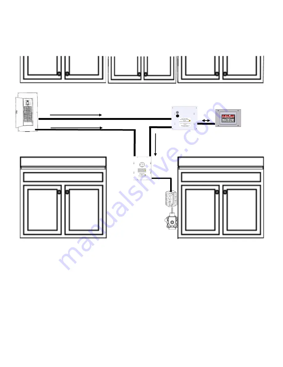
Clock Box PRO Stand-Alone Interface Diagram 

Non-

Plug‘N’Play


1.


Cable providing 120 VAC from Main Breaker Panel to the Clock Box PRO (not provided) 

a.


Connect the Line side to position four of the eight (8) position connector in the Clock Box PRO 
Control Box Power Plug 

b.


Connect the Neutral side to position two of the eight (8) position connector in the Clock Box PRO 
Control Box Power Plug 

c.


Connect the Ground side to position three of the eight (8) position connector in the Clock Box PRO 
Control Box Power Plug 

2.


24 VDC Input / Output Communication cable encased in 16 mm ENT Flexible Conduit (provided) 

a.


25 Ft in length 

b.


One communication (Ethernet) cable and one plenum cable  

c.


Connects to the Clock Box PLC and HMI / Touch Screen 

3.


120 VAC Output from the Clock Box PRO encased in 16 mm ENT Flexible Conduit (provided) 

Electrical Disconnect 

120 VAC Input (not provided) 

CB1 / CB2 

Summary of Contents for ClockBox Pro

Page 1: ...Clock Box PRO Installation and Operations Manual V1 1...

Page 2: ...hart Clock Box PRO Only 15 8 Touch Screen Mounting 16 17 9 ENT Flexible Conduit Installation 18 Operation and Setups 10 Operating the Clock Box PRO 19 11 Timer Setup 20 12 Password Setup and Reset 21...

Page 3: ...Installation work and electrical wiring must be done by a qualified person in accordance with all applicable codes and standards including fire rated construction codes and standards 4 When cutting o...

Page 4: ...m the Hood to the Junction Box c Run a new cable 4 not provided from the Junction Box to the Clock Box PRO Control Box d Wire nut the Hot leads from the three wires 1 3 4 together e Wire nut the Neutr...

Page 5: ...ht 8 position Power Plug in the Clock Box PRO Control Box 2 Connect the Neutral according to 4 b listed above 3 The Ground connects to position three of the eight 8 position Power Plug in the Clock Bo...

Page 6: ...Plug Input to Hood provided a 6 Ft in length b Power Cord from the Hood and connects to the 5 15R Receptacle not provided 3 120 VAC Output from Hood encased in 16 mm ENT Flexible Conduit provided a 10...

Page 7: ...n connectors i Labeled GD2 1 Located at the Gas Disconnect junction box ii Labeled GD3 1 Located at the Electrical Disconnect 6 24 VDC Input Output Communication cable encased in 16 mm ENT Flexible Co...

Page 8: ...Clock Box PRO Installation and Operations Manual V1 1 LAB 110218 8 Plug N Play Layout D1000 D1000 G and Clock Box PRO...

Page 9: ...Clock Box PRO Installation and Operations Manual V1 1 LAB 110218 9 Plug N Play Layout D1000 D1000 E and Clock Box PRO D1000 D1000 DED and Clock Box PRO...

Page 10: ...Clock Box PRO Installation and Operations Manual V1 1 LAB 110218 10 Device Flow Chart...

Page 11: ...o of the eight 8 position connector in the Clock Box PRO Control Box Power Plug c Connect the Ground side to position three of the eight 8 position connector in the Clock Box PRO Control Box Power Plu...

Page 12: ...Cable provided 10 Ft in length b One plenum cable Clock Box PRO Stand Alone Interface Diagram Non Plug N Play c Runs from the Clock Box PRO to the Power Source Disconnect 4 A jumper cable for the D100...

Page 13: ...C Input Output to from the Clock Box PRO encased in 16 mm ENT Flexible Conduit provided a 10 Ft in length b Two plenum cables c Runs from the Clock Box PRO to the Power Source Disconnect d Two four po...

Page 14: ...position connector i Label depends on the Power Source Disconnect option 1 D1000 DS E 120 220 a Labeled ED1 2 D1000 DS G a Labeled GD1 3 D1000 DS DRD a Labeled ED1 4 D1000 DS DED a D1000 DS E 120 220...

Page 15: ...Clock Box PRO Installation and Operations Manual V1 1 LAB 110218 15 Device Flow Chart Clock Box PRO Only...

Page 16: ...at a screw can go through to mount the touch screen enclosure to the wall secure the touch screen enclosure Note secure to studs or use an anchor 4 Attach the ethernet cable and power cable to the tou...

Page 17: ...screen enclosure mounting brackets to be adjusted depending on the thickness of the wall 4 On each bracket there are two holes for screws to go through to mount to the wall mount the touch screen enc...

Page 18: ...Connector on the three wire plenum cable and the ethernet cable are small enough to fit through the hole in the gland nut Reverse the process to reinstall the cable 3 To remove the Hood Interface Cabl...

Page 19: ...This displays the Clock Box Screen 5 The Clock Box PRO Screen display s the time remaining or if the system is paused After two minutes the screen will display the Main Screen 6 To start the timer pre...

Page 20: ...conds Press the empty box next to the desired time setting to change This displays the Time Input Screen 7 On the Time Input Screen input the desired time setting for the selected Hours Minutes or Sec...

Page 21: ...etup Screen 6 Press the empty box next to Enter New Password This displays the Password Entry Screen 7 Press the Clear Button to remove the current password from the box Enter the password that is to...

Page 22: ...ark press the Change Password Button A green check mark will appear next to the Change Password Button verifying the password is changed Password Reset 1 From the Main Screen press the Maintenance But...

Page 23: ...re three buttons one with a Light Bulb on it one with a Fan on it and with a House on it a The button with a Light Bulb powers ON and OFF the Hood light Note The Light Bulb button on the screen does n...

Page 24: ...Using the Number Pad enter the Password and press Enter This displays the Password Screen 4 Press OK This displays the Maintenance Screen 5 From the Maintenance Screen press the Language Button This D...

Page 25: ...ow 75psi The Range will not Power on a The Pressure in the D1000 Tank is low and cannot put out a fire The Range will not power on Inspect the Pressure Gauge on the top front of the Hood If the Arrow...

Page 26: ...that is 120VAC 8A ii If the displayed text reads Device On and the light is green the Clock Box PRO is energizing the power source disconnect or a device that is 120VAC 8A 2 Status LED a This display...

Page 27: ...Clock Box PRO Installation and Operations Manual V1 1 LAB 110218 27...

Page 28: ...late that a tank is installed a Press the HSW Off Button The text in the button switches to HSW On i This emulates that the tank s discharge hose as being connected b Press the PSW Off Button The text...

Page 29: ...ry Screen 3 Using the Number Pad enter the Password and press Enter This displays the Password Screen 4 Press OK This displays the Maintenance Screen 5 Press the Status button This displays the Status...

Page 30: ...ON Sending a signal to the building monitoring system or alarm system The Clock Box PRO provides a discreet COM NO and NC relay circuit To send a signal to the monitoring system the installer can con...

Page 31: ...e optional relay voltages sent with the Clock Box PRO are 120 VAC 24 VDC and 12 VDC Define the needed voltage and install the relay accordingly See below If an additional voltage is required please co...

Page 32: ...at is 120VAC 8A Note The Clock Box PRO comes with a 1A fuse if the device is over 1A then the F5 fuse has to be replaced with the applicable fuse type 5mm x 20mm cartridge 1 To enable the No Hood func...

Page 33: ...Clock Box PRO Installation and Operations Manual V1 1 LAB 110218 33 Troubleshooting Quick Guide...

Page 34: ...Clock Box PRO Installation and Operations Manual V1 1 LAB 110218 34 Clock Box PRO Schematic...

Page 35: ...Clock Box PRO Installation and Operations Manual V1 1 LAB 110218 35 Clock Box PRO Datasheet...

Page 36: ...Clock Box PRO Installation and Operations Manual V1 1 LAB 110218 36 Gas Disconnect Datasheet...

Page 37: ...Clock Box PRO Installation and Operations Manual V1 1 LAB 110218 37 Electrical Disconnect Datasheet...

Page 38: ...0 526 9846 F 860 526 9585 www denlarhoods com Service 860 526 9846 option 2 service denlarhoods com Sales 860 526 9846 option 1 sales denlarhoods com Warranty Information Specific warranty statement c...

Reviews: