


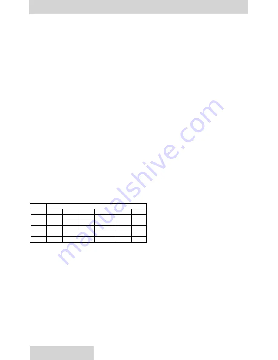
SPEED
GAGE PRESSURE
ABS. PRESS.
rpm
psig
bar
in. hg
mm hg
psi
bar
1200
-3
-0,2
-6.1
-155
11.7
0.8
1800
-3
-0,2
-6.1
-155
11.7
0.8
2100
-3
-0,2
-6.1
-155
11.7
0,8
2450
0
0
0
0
0
1,01
3000
6.3
0,44
12.8
326
22.1
1,52
INSTALLATION PROCEDURES, AND TECHNICAL SPECIFICATIONS AND LIMITS
78
GENERAL
The
DENISON HYDRAULICS
P07/P110 Series is a variable displacement open circuit axial piston pump with advance
pumping and control concepts.
MOUNTING
This pump is designed to operate in any position. The pump shaft must be in alignment with the shaft of the prime
mover and should be checked with a dial indicator. The mounting pad or adapter into which the pump pilots must be
concentric with the pump shaft to prevent bearing failure. This concentricity is particularly important if the shaft is rigidly
connected to the prime mover without a flexible coupling.
SHAFT INFORMATION
Splined
:
The shafts will accept a maximum misalignment of .006", 0.15 mm TIR. Angular misalignment at the male
and female spline axis must be less than 0.001 in. per in. radius, 0.001 mm per mm. The coupling interface must be
lubricated. DENISON HYDRAULICS recommends lithium molydisulfide or similar grease. The female coupling should
be hardened to 27-34 Rc. and must conform to SAE J498B (1971) class 1 flat root side fit. (P07), ISO 4156 fillet root
side fit module 1,00 or DIN 5480 (9H) flat root side fit module 2.00 as applicable. (P110)
Keyed
:
High strength heat treated keys must be used. Replacement keys must be hardened to 27-34 Rc. The key cor-
ners must be chamfered .030"-.040", 0.75-1.00 mm at 45° to clear radii that exist in the keyway.
PORTING INFORMATION
See port identification section for port locations and sizes.
The maximum case pressure is 25 psi, 1.7 bar continuous, 50 psi, 3.4 bar intermittent. Case pressures must never
exceed inlet pressure by more than 25 psi, 1.7 bar. When connecting case drain line make certain that drain plumbing
passes above highest point of the pump before returning to the reservoir, if not, install a 5 psi, 0.3 bar case pressure
check valve to be certain the case is filled with oil at all times.
The case drain line must be of sufficient size to prevent back pressure in excess of 25 psi, 1,7 bar and returned to the
reservoir below the surface of the oil as far from the supply suction as possible. All fluid lines, whether pipe, tubing, or
hose must be of adequate size and strength to assure free flow through the pump. An undersize inlet line will prevent
the pump from reaching full speed and torque. An undersized outlet line will create back pressure and cause improper
operation. Flexible hose lines are recommended. If rigid piping is used, the workmanship must be accurate to elimi-
nate strain on the pump port block or to the fluid connections. Sharp bends in the lines must be eliminated wherever
possible. All system piping must be cleaned with solvent or equivalent before installing pump. Make sure the entire
hydraulic system is free of dirt, lint, scale, or other foreign material.
CAUTION:
Do not use galvanized pipe. Galvanized coating can flake off with continued use.
INLET CONDITIONS AT SEA LEVEL, FULL DISPLACEMENT
NOTE:
Inlet conditions apply for petroleum base fluids. Contact
DENISON HYDRAULICS
for inlet conditions with
other fluids.
RECOMMENDED FLUIDS
See DENISON HYDRAULICS bulletin
SPO-AM305
for more information
MAINTENANCE
This pump is self-lubricating and preventative maintenance is limited to keeping system fluid clean by changing filters
frequently. Keep all fittings and screws tight. Do not operate at pressures and speeds in excess of the recommended
limit. If the pump does not operate properly, check the troubleshooting chart before attempting to overhaul the unit.
Overhauling is relatively simple and may be accomplished by referring to the disassembly, rework limits of wear parts
and assembly procedures.
FLUID CLEANLINESS
Fluid must be cleaned before adding to the system, and continuously during operation by filters that maintain a cleanli-
ness level of NAS 1638 Class 8. This approximately corresponds to ISO 17/14.
www.comoso.com
Summary of Contents for P07 C-mod
Page 54: ...PQ HIGH RESPONSE CONTROL 54 PQ CONTROL IN PROCESS OF DEVELOPMENT www comoso com ...
Page 55: ...PQ HIGH RESPONSE CONTROL 55 PQ CONTROL IN PROCESS OF DEVELOPMENT www comoso com ...
Page 56: ...PQ HIGH RESPONSE CONTROL 56 PQ CONTROL IN PROCESS OF DEVELOPMENT www comoso com ...
Page 57: ...PQ HIGH RESPONSE CONTROL 57 PQ CONTROL IN PROCESS OF DEVELOPMENT www comoso com ...
Page 74: ...74 TEST PROCEDURE PQ CONTROL IN PROCESS OF DEVELOPMENT www comoso com ...