


52
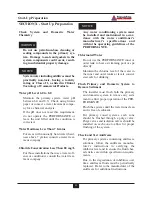
Start-Up Preparation
Verify Correct Pressure Switch
1. Remove the burner hood and verify the
burner pressure switch setting.
2. Check and compare the color of the out-
line on the pressure switch label to Table
4 page 51.
The PERFORMANCE is equipped with
an air pressure switch, which provides a
safe means of shutting down the unit due
to a blockage of the combustion air inlet.
The switch is “normally closed” and
measures the change in the negative
pressure (vacuum) created by the burn-
er blower.
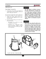
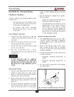
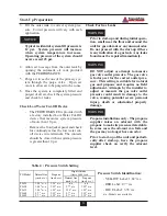
Verify Correct Air Shutter Setting
-
Check and verify the air shutter setting
as listed in Table 5.
-
The air shutter is located inside the com-
bustion air inlet adapter located in the
top /left jacket panel area. See Fig. 37.
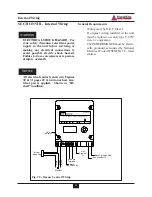
Check Thermostat Circuit
-
Unplug the Room Thermostat Snap-set
located on the rear of the unit.
-
Connect a voltmeter across the end ter-
minals of the male half of the Room
Thermostat Snap-set.
-
Close each thermostat, zone valve and
relay in the external circuit one zone at
a time and check the voltage reading
across the plug.
-
There should
NEVER
be voltage mea-
sured at the plug.
-
If voltage is measured at the plug under
any condition, check and correct the
external wiring.
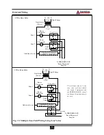
In systems using 3-wire zone valves
backfeed of voltage to the unit is a com-
mon problem. Use an isolation relay to
prevent voltage from the external circuit
entering the Room Thermostat Snap-set.
See Fig. 33, page 46.
NOTICE
NOTICE
Table 5 : Air Shutter Settings
Fig. 37: Air Shutter Adjustment
Model
Natural gas Propane
Natural gas
Propane
Natural gas Propane
Natural gas
Propane
PG-25
N/R
3.5
n/a
n/a
n/a
n/a
n/a
n/a
PG-30
N/R
3.5
4.5
4.5
2.5
4.0
n/a
n/a
PG-35
N/R
3.5
4.5
3.5
3.5
3.75
n/a
n/a
PG-40
N/R
0
2
0
0
0
n/a
n/a
PG-45
N/R
0
0
0
0
0
0
0
9,000 feet elevation
8,000 feet elevation
5,000 feet elevation
n/a -Models not available.
N/R - Air Shutter not required. (For these units an adjustable air shutter is NOT supplied with the unit.)