Model 9320-150 Installation Instructions
Page 6 of 13
Document: RDS-INS9293V, Rev. C
Do not copy or distribute without written permission. Unpublished Work
2019 Delphi Display Systems, Inc. All rights reserved.
Printed copies are Uncontrolled unless clearly marked as a Controlled document. User is responsible for verifying document is the current revision.
4.2
Display Mounting Options
The Model 9320 V-Net Display Module can be mounted using a variety of different mounting enclosures.
Depending on the type of mounting option (canopy, speaker stand, menu board, etc.), Delphi may either
supply part or all of the necessary equipment. Please refer to the appropriate manual for the different
mounting options.
5
Installation Procedures
5.1
Display Installation
Install the 9320 V-Net Display Module into the applicable mounting option utilizing the supplied mounting
instructions. Once the Display is installed, pull the supplied CAT5E cable from the display to the location of
the external PC or video server.
5.2
CAT5 Cable Termination at the Display
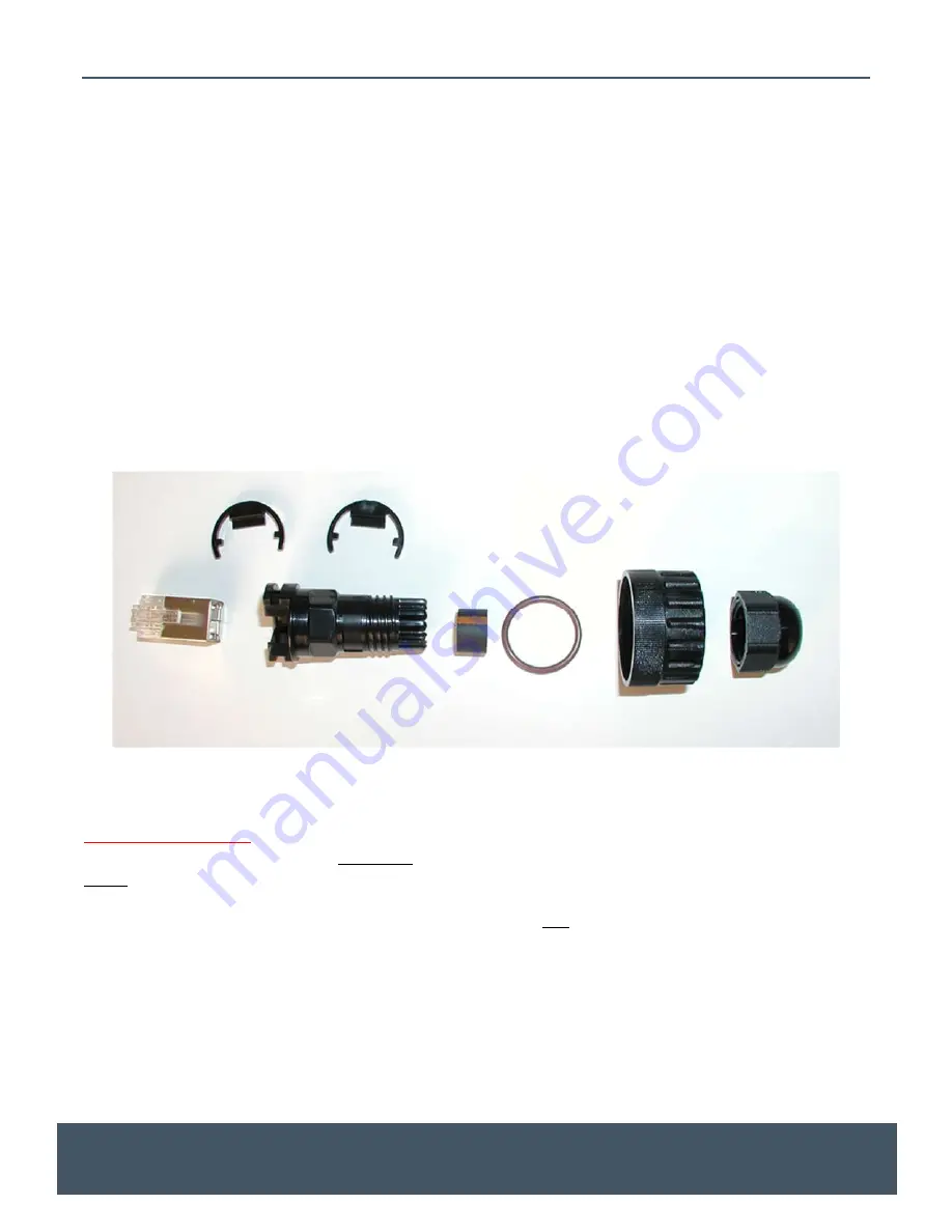
The CAT5E cable should be terminated and connected to the back of the display using the supplied
waterproof RJ45 Field Connector Kit as seen in the figure below.
Note: Failure to use the supplied
waterproof connector will void the system warranty!
Figure 4 - Detail of Watertight Field Connector Kit
Very Important
The Field Connector Kit contains a
SHIELDED
RJ45 connector as shown on the right below. This connector
MUST
be used on the back of the display. Use of any other type of connector on the back of the display will
result in a loose connection, and will void the customer’s warranty. Although the shielded connector is
necessary, it is not actually used as a shield, so shield wires will
not
be connected to it.


