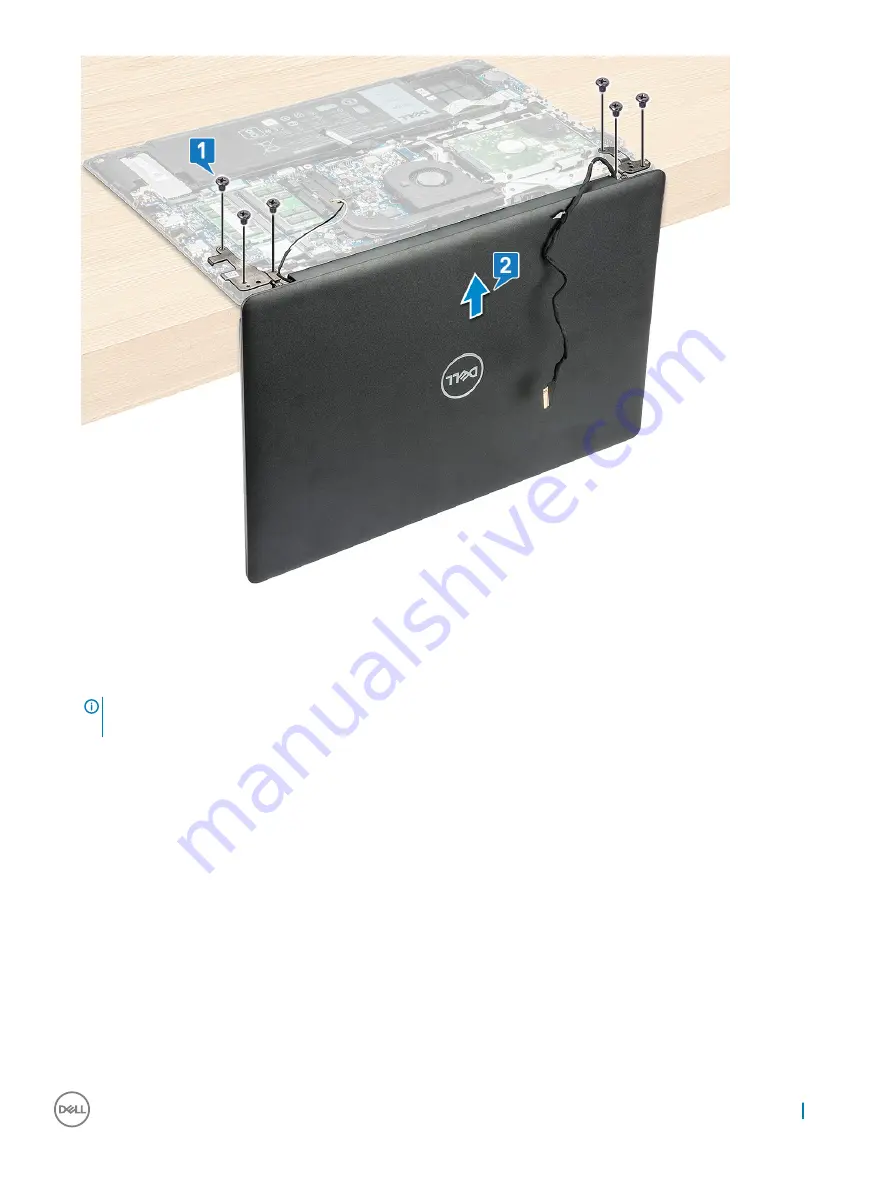
Installing the display assembly
1
Place the display assembly on the palm rest at a 90 degree angle and align with the screw holders on the palm rest.
NOTE:
Hold the display assembly firmly when you place the display assembly on the plamrest at a 90 degree angle, to avoid
damaging the display assembly.
2
Tighten the 6 M2.5x2.5 screws to secure the display assembly to the computer.
3
Turn over the computer
4
Route the WLAN cables through the routing channel.
5
For models shipped with a WWAN card, the WWAN antennas must be routed underneath the right display hinge and above the VGA
daughter board cable, and then secured with an adhesive tape on the power button daughter board.
6
Route the eDP cable through the hook of the right LCD hinge and routing clips on the system.
7
Affix the adhesive tape to secure the eDP cable to the system.
8
Route the display cable through the routing channel on the system fane and connect the display cable to its connector on the system
board.
9
Install the:
a
b
c
d
10 Follow the procedure in
After working inside your computer
Removing and installing components
39
Summary of Contents for Vostro 3590
Page 1: ...Latitude 3590 Owner s Manual Regulatory Model P75F Regulatory Type P75F001 ...
Page 15: ...4 Lift the base cover away from the computer Removing and installing components 15 ...
Page 34: ...c Lift the fingerprint reader off the computer 34 Removing and installing components ...
Page 94: ...94 Software ...


