


3
Affix the adhesive tape to secure the touchpad to the system.
4
Align and place the metal bracket under the plastic hold down.
5
Replace the two M2x2 screws to secure the metal bracket to the touchpad.
6
Install the:
a
b
7
Follow the procedure in
After working inside your computer
.
Display assembly
Removing the display assembly
1
Follow the procedure in
Before working inside your computer
.
2
Remove the:
a
b
c
d
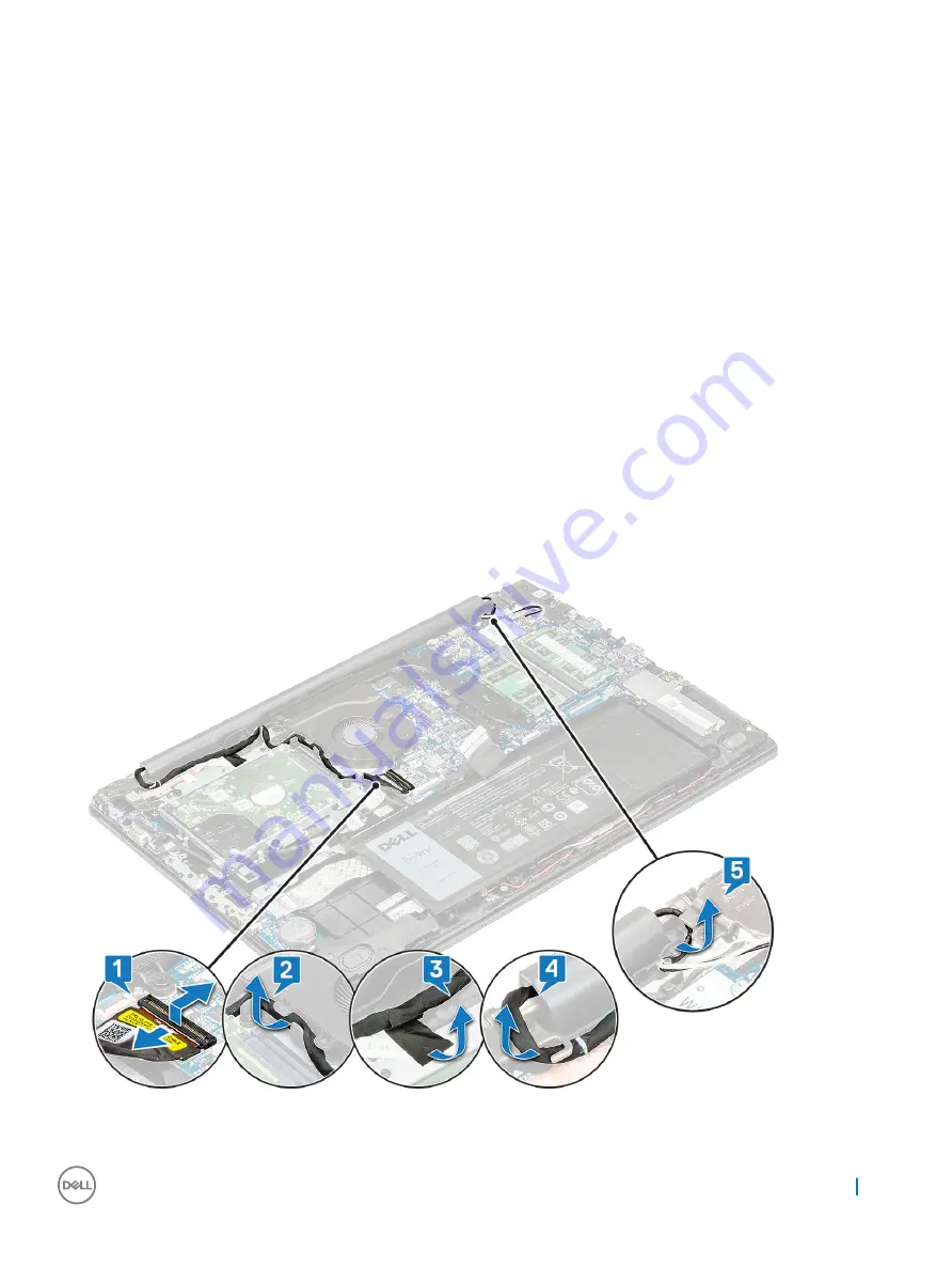
3
Remove the eDP cable from its connector on the system board [1] and unroute the cable from the routing channel on the system fan
[2].
4
Peel off the adhesive tape securing the eDP cable to the system [3].
5
Unroute the eDP cable from the hook of the right LCD hinge and routing clips on the system [4].
6
Unroute the WLAN cables from the routing channel [5] .
7
Then, open the palm-rest assembly to at least 90-degrees and place the system on the edge of a table so that the palm rest is laying
flat on the table and the display assembly is over the edge.
Removing and installing components
37
Summary of Contents for Vostro 3590
Page 1: ...Latitude 3590 Owner s Manual Regulatory Model P75F Regulatory Type P75F001 ...
Page 15: ...4 Lift the base cover away from the computer Removing and installing components 15 ...
Page 34: ...c Lift the fingerprint reader off the computer 34 Removing and installing components ...
Page 94: ...94 Software ...


