connector
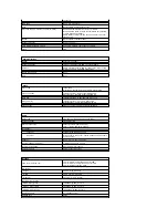
IEEE 1394
One 4-pin -connector
Dock
Optional USB Port Replicator only
Mini-card support (internal expansion slots)
One dedicated half Mini-Card slot for WLAN
One dedicated full Mini-Card slot for WPAN (Bluetooth
®
or ultra wideband [UWB])
WPAN full Mini-Card slot can also be used for the Intel
Flash Cache
Modem
Optional USB external modem
Network adapter
RJ-45 connector
USB, USB PowerShare, eSATA
Four 4-pin USB 2.0-compliant connectors
Video
VGA
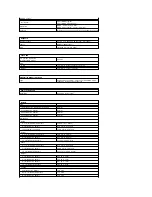
Communications
Modem
External (optional)
Network adapter
10/100/1000 Ethernet LAN on system board
Wireless
WLAN half Mini-Card, WPAN full Mini-Cards, Bluetooth
®
wireless support, and UWB technology
Mobile Broadband
None
GPS
None
Video
Video type
Integrated
Discrete on system board, hardware accelerated
Video controller
Integrated video: Mobile Intel GMA X4500
Discrete video: NVIDIA GeForce 9300M GS
Data bus
Integrated video or PCI-Express video x16
Video memory
Integrated video: up to 256 MB shared
Discrete video: 256 MB dedicated memory
Video output
Video connector and multimode DisplayPort
Audio
Audio type
Two-channel high-definition audio codec
Audio controller
IDT 92HD71B5
Stereo conversion
24-Bit (stereo digital-to-analog)
24-Bit (stereo analog-to-digital)
Interfaces:
Internal
Internal High Definition Audio
External
Microphone-in connector, stereo headphones/speakers
mini-connector
Speaker
One 2-watt, 4-ohm speakers
Internal speaker amplifier
1-Watt channel into 4 ohms
Internal microphone
Single digital microphone
Volume controls
Volume control buttons
Display
Type (active-matrix TFT)
15.4" WXGA w/anti-glare CCFL or WLED
15.4" WXGA+ w/anti-glare CCFL or WLED
15.4" WUXGA TrueLife!" CCFL
Dimensions
Height
225.5 mm (8.8 inches)
Width
344.5 mm (13.6 inches)
Diagonal
391.16 mm (15.4 inches)
Maximum Resolutions
WXGA w/anti
-glare
1280x800 at 262 K colors
WXGA+ w/anti
-glare
1440x900 at 262 K colors
WUXGA with TrueLife
1920X1200 at 262 K colors
Operating angle
0° (closed) to 160°
Refresh rate
60 Hz
Summary of Contents for Vostro 1520
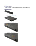
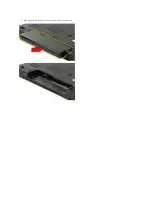
Page 12: ...4 Slide the battery itself toward the back of the computer and remove ...
Page 14: ......
Page 16: ...5 Remove the bezel from the display assembly ...
Page 19: ......
Page 22: ......
Page 25: ......
Page 27: ......
Page 31: ......
Page 33: ...6 Lift the fan and remove it from the computer ...
Page 36: ...15 Remove the fingerprint reader from the palm rest ...
Page 40: ......
Page 42: ...5 Remove the hard drive and mini card access panel ...
Page 45: ......
Page 47: ...5 Remove the memory module from the socket ...
Page 49: ...6 Remove the optical drive from the computer ...
Page 53: ......
Page 55: ...5 Remove the access panel ...
Page 58: ......
Page 60: ......
Page 63: ......
Page 66: ...15 Lift the inside edge of the USB board and remove the board from the computer ...
Page 67: ......
Page 69: ......
Page 72: ......
Page 74: ......


