


Figure 65. Removing an FCM
4. While supporting the FCM with both hands, remove it from the enclosure.
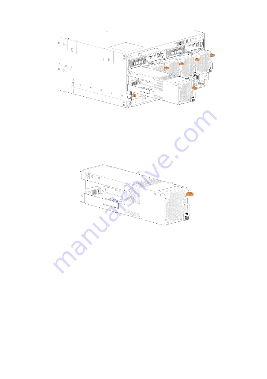
Installing a fan cooling module
You can hotswap the replacement of a single fan cooling module. However, if you are replacing multiple fan cooling module, the
enclosure must be powered off using an orderly shutdown using the management interfaces.
1. Orient the fan cooling module (FCM) for insertion into the target slot on the enclosure rear panel.
Figure 66. Installing an FCM
2. Slide the FCM into the slot until the latch clicks home.
The enclosure should automatically detect and make use of the new module.
3. Wait for the Module OK LED on the newly inserted FCM to illuminate green.
●
If the Module OK LED does not illuminate, verify that the FCM is properly inserted and seated in the slot.
●
If properly seated, the module may be defective. Check the PowerVault Manager and the event logs for more
information.
●
Using the management interfaces (the PowerVault Manager or CLI), determine if the health of the new FCM is OK.
Verify that the Module OK LED is green, and that the Ops panel states show no amber module faults.
4. If replacing multiple FCMs, repeat steps 1 through 3.
Completing the component installation process
This section provides a procedure for ensuring that the components installed in the replacement controller enclosure chassis
function properly.
1. Reconnect data cables between devices, as needed, to return to the original cabling configuration:
●
Between cascaded storage enclosures.
●
Between the controller and peripheral or SAN devices.
Module removal and replacement
69


