background image

9.

Reconnect the system to the electrical outlet and turn the system on, including any attached 
peripherals.

Cooling Shroud

Removing The Cooling Shroud

CAUTION: Many repairs may only be done by a certified service technician. You should only 
perform troubleshooting and simple repairs as authorized in your product documentation, or as 
directed by the online or telephone service and support team. Damage due to servicing that is 

not authorized by Dell is not covered by your warranty. Read and follow the safety instructions 

that came with the product.

CAUTION: Never operate your system without the cooling shroud. The system may get 

overheated, which may result in loss of performance.

1.

Turn off the system, including any attached peripherals, and disconnect the system from the 

electrical outlet and peripherals.

2.

Open the system.

3.

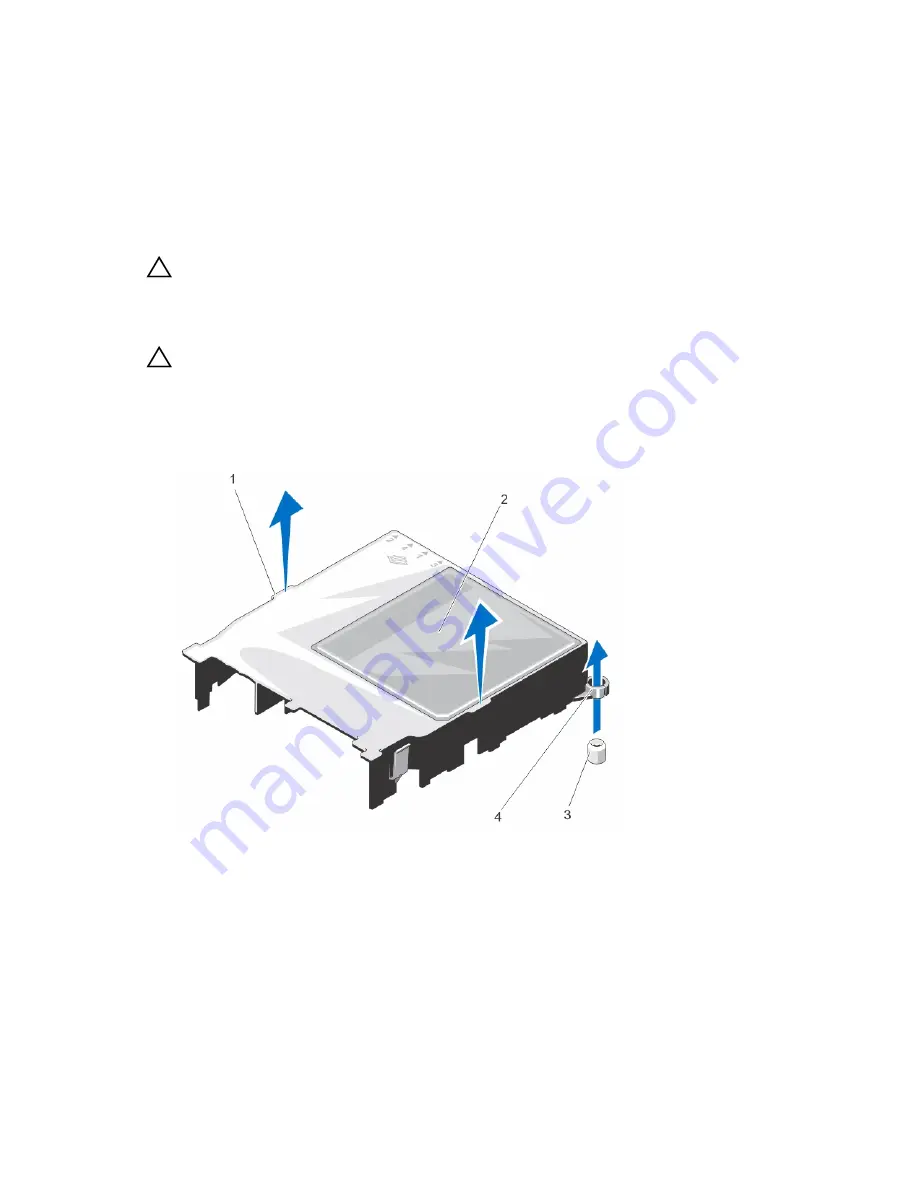
Hold the touch points and lift the cooling shroud away from the system.

Figure 16. Removing and Installing the Cooling Shroud

1.

cooling-shroud touch points

2. cooling shroud 

3. cooling-shroud guide screws (2)

4. cooling-shroud guide screw slots (2)

43

Summary of Contents for PowerEdge R220

Page 1: ...Dell PowerEdge R220 Owner s Manual Regulatory Model E10S Regulatory Type E10S003 ...

Page 2: ...problem WARNING A WARNING indicates a potential for property damage personal injury or death Copyright 2015 Dell Inc All rights reserved This product is protected by U S and international copyright and intellectual property laws Dell and the Dell logo are trademarks of Dell Inc in the United States and or other jurisdictions All other marks and names mentioned herein may be trademarks of their res...

Page 3: ... 25 iDRAC Settings Utility 25 3 Installing System Components 26 Recommended Tools 26 Front Bezel Optional 26 Installing The Front Bezel 26 Removing The Front Bezel 26 Opening And Closing The System 27 Opening The System 27 Closing The System 28 Inside The System 28 Chassis Intrusion Switch 29 Removing The Chassis Intrusion Switch 29 Installing The Chassis Intrusion Switch 30 Optical Drive Optional...

Page 4: ...ines 45 Sample Memory Configurations 45 Removing Memory Modules 46 Installing Memory Modules 47 Internal USB Memory Key Optional 48 Removing And Installing The Internal USB Key 48 Expansion Cards And Expansion Card Risers 49 Expansion Card Installation Guidelines 49 Expansion Card Types And Form Factor 49 Removing An Expansion Card 50 Installing An Expansion Card 51 Removing The Expansion Card Ris...

Page 5: ...ling Problems 68 Troubleshooting Cooling Fans 68 Troubleshooting System Memory 68 Troubleshooting An Internal USB Key 69 Troubleshooting An SD Card 70 Troubleshooting An Optical Drive 70 Troubleshooting A Hard Drive 71 Troubleshooting Expansion Cards 71 Troubleshooting The Processor 72 5 Using System Diagnostics 73 Dell Embedded System Diagnostics 73 When To Use The Embedded System Diagnostics 73 ...

Page 6: ...Alert Messages 91 9 Getting Help 92 Contacting Dell 92 Locating Your System Service Tag 92 Documentation Feedback 92 Quick Resource Locator 92 ...

Page 7: ...hutdown before power to the system is turned off 2 NMI button Used to troubleshoot software and device driver errors when running certain operating systems This button can be pressed using the end of a paper clip Use this button only if directed to do so by qualified support personnel or if the information is provided in the operating system documentation 3 Video connector Allows you to connect a ...

Page 8: ...racket is removed Ambient temperature is too high External airflow is obstructed See Getting Help 8 System status indicator Lights blue during normal system operation Lights amber when the system needs attention due to a problem See the System Event Log or system messages for the specific issue Invalid memory configurations can cause the system to halt at startup without any video output See Getti...

Page 9: ...rd slot optional Allows you to connect the optional vFlash media card 3 Serial connector Allows you to connect a serial device to the system 4 PCIe expansion card slot Allows you to connect one low profile PCI Express expansion card 5 Video connector Allows you to connect a VGA display to the system 6 eSATA Allows you to connect additional storage devices 7 USB connectors 2 Allow you to connect US...

Page 10: ...wer supply 12 Retention clip Secures the power cable NIC Indicator Codes Figure 3 NIC Indicator 1 link indicator 2 activity indicator Indicator Indicator Code Link and activity indicators are off The NIC is not connected to the network Link indicator is green The NIC is connected to a valid network at its maximum port speed 1 Gbps or 10 Gbps Link indicator is amber The NIC is connected to a valid ...

Page 11: ...ips with your system provides documentation and tools for configuring and managing your system including those pertaining to the operating system system management software system updates and system components that you purchased with your system The Administrator s Guide which provides information about configuring and managing the system NOTE Always check for updates on dell com support manuals a...

Page 12: ...nters the BIOS Boot Manager or the Unified Extensible Firmware Interface UEFI Boot Manager depending on the system s boot configuration F12 Starts Preboot Execution Environment PXE boot From the System Setup you can Change the NVRAM settings after you add or remove hardware View the system hardware configuration Enable or disable integrated devices Set performance and power management thresholds M...

Page 13: ... DOS and 32 bit operating systems do not support UEFI and can only be installed from the BIOS boot mode NOTE For the latest information on supported operating systems go to dell com ossupport Entering System Setup 1 Turn on or restart your system 2 Press F2 immediately after you see the following message F2 System Setup If your operating system begins to load before you press F2 allow the system t...

Page 14: ...figuration NOTE System Setup defaults are listed under their respective options in the following sections where applicable Menu Item Description System Information Displays information about the system such as the system model name BIOS version Service Tag and so on Memory Settings Displays information and options related to installed memory Processor Settings Displays information and options rela...

Page 15: ...urer Displays the name of system manufacturer System Manufacturer Contact Information Displays the contact information of the system manufacturer System CPLD Version Displays the CPLD version of the system Memory Settings Screen Menu Item Description System Memory Size Displays the amount of memory installed in the system System Memory Type Displays the type of memory installed in the system Syste...

Page 16: ...led DCU Streamer Prefetcher Allows you to enable or disable Data Cache Unit streamer prefetcher By default the DCU Streamer Prefetcher option is set to Enabled DCU IP Prefetcher Allows you to enable or disable Data Cache Unit IP prefetcher By default the DCU IP Prefetcher option is set to Enabled Execute Disable Allows you enable or disable execute disable memory protection technology By default t...

Page 17: ...disables the UEFI Boot Settings menu Boot Sequence Retry Allows you to enable or disable the boot sequence retry feature If this field is enabled and the system fails to boot the system reattempts the boot sequence after 30 seconds By default the Boot Sequence Retry option is set to Disabled BIOS Boot Settings Allows you to enable or disable BIOS Boot options NOTE This option is enabled only if th...

Page 18: ...ver are disabled Serial Communications Screen Menu Item Description Serial Communication Allows you to select serial communication devices Serial Device 1 and Serial Device 2 in the BIOS BIOS console redirection can also be enabled and the port address used can be specified By default Serial Communication option is set to On without Console Redirection Serial Port Address Allows you to set the por...

Page 19: ...fault the Memory Frequency option is set to Maximum Performance Turbo Boost Allows you to enable or disable the processor to operate in turbo boost mode By default the Turbo Boost option is set to Enabled C1E Allows you to enable or disable the processor to switch to a minimum performance state when it is idle By default the C1E option is set to Enabled C States Allows you to enable or disable the...

Page 20: ... Allows you to enable or disable the power button on the front of the system By default the Power Button option is set to Enabled NMI Button Allows you to enable or disable the NMI button on the front of the system By default the NMI Button option is set to Disabled AC Power Recovery Allows you to set how the system reacts after AC power is restored to the system By default the AC Power Recovery o...

Page 21: ...re disabled Assigning A System And Or Setup Password NOTE The password jumper enables or disables the System Password and Setup Password features For more information on the password jumper settings see System Board Jumper Settings You can assign a new System Password and or Setup Password or change an existing System Password and or Setup Password only when the password jumper setting is enabled ...

Page 22: ...ity and press Enter The System Security screen is displayed 4 In the System Security screen verify that Password Status is Unlocked 5 Select System Password alter or delete the existing system password and press Enter or Tab 6 Select Setup Password alter or delete the existing setup password and press Enter or Tab NOTE If you change the System and or Setup password a message prompts you to re ente...

Page 23: ... cannot disable or change an existing system password NOTE You can use the Password Status option in conjunction with the Setup Password option to protect the system password from unauthorized changes Entering The UEFI Boot Manager NOTE Operating systems must be 64 bit UEFI compatible for example Microsoft Windows Server 2012 to be installed from the UEFI boot mode DOS and 32 bit operating systems...

Page 24: ...Boot Menu Displays the list of available BIOS boot options marked with asterisks Select the boot option you wish to use and press Enter UEFI Boot Menu Displays the list of available UEFI boot options marked with asterisks Select the boot option you wish to use and press Enter The UEFI Boot Menu enables you to Add Boot Option Delete Boot Option or Boot From File Driver Health Menu Displays a list o...

Page 25: ...e various iDRAC parameters using the iDRAC Settings Utility NOTE Accessing some of the features on the iDRAC Settings Utility requires the iDRAC7 Enterprise License upgrade For more information on using iDRAC see the iDRAC7 User s Guide at dell com esmmanuals Entering The iDRAC Settings Utility 1 Turn on or restart the managed system 2 Press F2 during Power on Self test POST 3 In the System Setup ...

Page 26: ...nd Front Bezel Optional Installing The Front Bezel 1 Hook the right end of the bezel onto the chassis 2 Fit the free end of the bezel onto the chassis 3 Secure the bezel with the keylock Figure 4 Installing and Removing the Front Bezel 1 release latch 2 keylock 3 front bezel 4 locking hook Removing The Front Bezel 1 Unlock the keylock at the left end of the bezel 2 Lift the release latch next to t...

Page 27: ...ed by Dell is not covered by your warranty Read and follow the safety instructions that came with the product CAUTION Do not operate the system without the cover for a duration exceeding five minutes CAUTION Always use a static mat and static strap while working on components in the interior of the system Opening The System 1 Turn off the system and attached peripherals and disconnect the system f...

Page 28: ...tified service technician You should only perform troubleshooting and simple repairs as authorized in your product documentation or as directed by the online or telephone service and support team Damage due to servicing that is not authorized by Dell is not covered by your warranty Read and follow the safety instructions that came with the product Figure 6 Inside the System 1 2 5 inch HDD0 1 or 3 ...

Page 29: ...orized in your product documentation or as directed by the online or telephone service and support team Damage due to servicing that is not authorized by Dell is not covered by your warranty Read and follow the safety instructions that came with the product 1 Turn off the system including any attached peripherals and disconnect the system from the electrical outlet and peripherals 2 Open the syste...

Page 30: ... simple repairs as authorized in your product documentation or as directed by the online or telephone service and support team Damage due to servicing that is not authorized by Dell is not covered by your warranty Read and follow the safety instructions that came with the product 1 If installed remove the front bezel 2 Turn off the system including any attached peripherals and disconnect the syste...

Page 31: ...epairs as authorized in your product documentation or as directed by the online or telephone service and support team Damage due to servicing that is not authorized by Dell is not covered by your warranty Read and follow the safety instructions that came with the product 1 If installed remove the front bezel 2 Turn off the system including any attached peripherals and disconnect the system from th...

Page 32: ...formance and reliability to be optimized for the target implementation NOTE Do not mix Enterprise Class Drives with Entry Hard Drives Choosing the right drive type depends on the usage pattern Improper use of Entry Hard Drives workload rating exceed 55TB year will lead to significant risk and increase the drives failure rate For more information on these hard drives see the 512e and 4Kn Disk Forma...

Page 33: ...ables are connected to the PERC card cable adapter To disconnect the power and data cables remove the PERC card cable adapter from the hard drive 5 If applicable remove the optical drive installed on top of the hard drive cage HDD1 For more information on removing the optical drive see Removing The Optical Drive 6 Pull the release pin slide the hard drive cage away from the chassis wall 7 Lift the...

Page 34: ... drive cage 5 Connect the power and data cables to the hard drive If connecting to the integrated SATA controller SATA hard drives only connect the SATA data cable to the SATA connector on the system board If connecting to a SAS RAID controller card SAS or SATA hard drives connect the data cable to the connector on the card edge If you have installed a PERC card connect the power and data cables t...

Page 35: ...Insert the hard drive into the hard drive cage 2 Align the screw holes on the hard drive with the screw holes on the hard drive cage 3 Install the screws to secure the hard drive to the hard drive cage Removing A 2 5 Inch Hard Drive Cage CAUTION Many repairs may only be done by a certified service technician You should only perform troubleshooting and simple repairs as authorized in your product d...

Page 36: ...n You should only perform troubleshooting and simple repairs as authorized in your product documentation or as directed by the online or telephone service and support team Damage due to servicing that is not authorized by Dell is not covered by your warranty Read and follow the safety instructions that came with the product 1 If installed remove the front bezel 2 Turn off the system and attached p...

Page 37: ...m The Hard Drive Cage 1 Remove the screws from the side of the hard drive cage 2 Remove the hard drive from the hard drive cage Figure 12 Removing and Installing a 2 5 Inch Hard Drive Into the Hard Drive Cage 1 screws 4 2 2 5 inch hard drive cage 3 2 5 inch hard drive Installing A 2 5 Inch Hard Drive Into The Hard Drive Cage CAUTION Many repairs may only be done by a certified service technician Y...

Page 38: ...by your warranty Read and follow the safety instructions that came with the product 1 Turn off the system including any attached peripherals 2 Disconnect the power cable from the power source 3 Remove the bezel if applicable 4 Insert a screw driver into the notch and pull out the LED label NOTE Retain the removed LED label for future use 5 Remove the screws securing the LED module to the chassis 6...

Page 39: ...ld only perform troubleshooting and simple repairs as authorized in your product documentation or as directed by the online or telephone service and support team Damage due to servicing that is not authorized by Dell is not covered by your warranty Read and follow the safety instructions that came with the product 1 If installed remove the front bezel 2 Turn off the system including any attached p...

Page 40: ...rvicing that is not authorized by Dell is not covered by your warranty Read and follow the safety instructions that came with the product 1 Insert the control panel module into the slot in the chassis and align the two screw holes on the control panel module with the corresponding holes on the chassis 2 Secure the control panel board with the screws 3 Connect all the applicable cables to the contr...

Page 41: ...le repairs as authorized in your product documentation or as directed by the online or telephone service and support team Damage due to servicing that is not authorized by Dell is not covered by your warranty Read and follow the safety instructions that came with the product CAUTION Do not operate the system with the cover removed for a duration exceeding five minutes NOTE The procedure for removi...

Page 42: ...ollow the safety instructions that came with the product 1 Turn off the system including any attached peripherals and disconnect the system from the electrical outlet 2 Open the system 3 Remove the cooling shroud 4 Orient the fan module so that the side with the power cable faces the back of the system NOTE Install fan 3 if you are installing an expansion card Remove the fan Mylar from the fan 3 s...

Page 43: ...orized by Dell is not covered by your warranty Read and follow the safety instructions that came with the product CAUTION Never operate your system without the cooling shroud The system may get overheated which may result in loss of performance 1 Turn off the system including any attached peripherals and disconnect the system from the electrical outlet and peripherals 2 Open the system 3 Hold the ...

Page 44: ...d 2 Lower the cooling shroud into the chassis until all edges are secured to the system board When firmly seated the memory socket numbers marked on the cooling shroud align with the respective memory sockets 3 Close the system 4 Reconnect the system to the electrical outlet and turn the system on including any attached peripherals System Memory Your system supports DDR3 unbuffered ECC DIMMs It su...

Page 45: ...er first in sockets with white release levers and then black For example if you want to mix quad rank and dual rank DIMMs populate quad rank DIMMs in the sockets with white release tabs and dual rank DIMMs in the sockets with black release tabs Memory modules of different sizes can be mixed provided that other memory population rules are followed for example 4 GB and 8 GB memory modules can be mix...

Page 46: ... to servicing that is not authorized by Dell is not covered by your warranty Read and follow the safety instructions that came with the product 1 Turn off the system including any attached peripherals and disconnect the system from the electrical outlet and peripherals 2 Open the system 3 Remove the cooling shroud 4 Locate the appropriate memory module socket s 5 To release the memory module from ...

Page 47: ... the memory module socket down and out to allow the memory module to be inserted into the socket 6 Align the memory module s edge connector with the alignment key of the memory module socket and insert the memory module in the socket CAUTION To prevent damage to the memory module socket during installation apply pressure at both ends of the memory module evenly Do not apply pressure to the center ...

Page 48: ...USB Key CAUTION Many repairs may only be done by a certified service technician You should only perform troubleshooting and simple repairs as authorized in your product documentation or as directed by the online or telephone service and support team Damage due to servicing that is not authorized by Dell is not covered by your warranty Read and follow the safety instructions that came with the prod...

Page 49: ...are installing an expansion card purchase and install fan 3 Your system supports one of the following expansion cards PCI Express Generation 3 expansion card PERC H310 H710 H810 NOTE When you install a PERC card connect the data and power cables to the hard drive using a PERC card cable adapter Expansion Card Types And Form Factor The following table describes the types of expansions cards and the...

Page 50: ...ard riser 4 Lift and rotate the expansion card latch 5 Hold the expansion card by its edges and slide the card out to remove it from the connector on the expansion card riser 6 If you are removing the card permanently install a metal filler bracket over the empty expansion slot opening and close the expansion card latch NOTE You must install a filler bracket over an empty expansion slot to maintai...

Page 51: ...at the expansion card is properly seated along the chassis so that the expansion card latch can be closed 9 Close the expansion card latch 10 Connect the cables to the expansion card 11 Close the system 12 Reconnect the system to the electrical outlet and turn the system on including any attached peripherals 13 Install any device drivers required for the card as described in the documentation for ...

Page 52: ...ized by Dell is not covered by your warranty Read and follow the safety instructions that came with the product 1 Align the expansion card riser with the connector and the guide pins on the system board 2 Lower the expansion card riser into place until the expansion card riser is fully seated in the connector 3 If applicable reinstall the expansion card into the expansion card riser For more infor...

Page 53: ...card 6 Pull back slightly on the two tabs at the front edge of the card and gently lift the front edge of the card off the standoffs As the card releases from the standoffs the connector under the card disengages from the system board connector 7 Slide the card away from the back of the system until the RJ 45 connector is clear of the back panel then lift the card out of the chassis 8 If applicabl...

Page 54: ...y attached peripherals and disconnect the system from the electrical outlet and peripherals 3 Open the system 4 If installed remove the expansion card from the expansion slot 5 Remove the plastic filler plug for the iDRAC7 Enterprise port from the system back panel 6 Orient the card so that the RJ 45 connector at the bottom of the card passes through the back panel opening 7 Align the slots on the...

Page 55: ...tem including any attached peripherals and disconnect the system from the electrical outlet and peripherals 2 Open the system 3 Locate the battery socket CAUTION To avoid damage to the battery connector you must firmly support the connector while installing or removing a battery 4 Pull the release pin back and lift the system battery out of the battery connector 5 To install a new system battery p...

Page 56: ...s and disconnect the system from the electrical outlet When disconnected from AC power press and hold the power button for three seconds to fully drain the system of stored power prior to removing the cover 3 Open the system 4 Remove the cooling shroud WARNING The heat sink and processor are hot to the touch for some time after the system has been powered down Allow the heat sink and processor to ...

Page 57: ...ssor socket release lever and release the lever from the locked position by pushing down and out from under the tab Rotate the lever upward 10 Rotate the processor shield upward and out of the way CAUTION The socket pins are fragile and can be permanently damaged Be careful not to bend the pins in the socket when removing the processor out of the socket 11 Lift the processor out of the socket and ...

Page 58: ...nline or telephone service and support team Damage due to servicing that is not authorized by Dell is not covered by your warranty Read and follow the safety instructions that came with the product 1 Before upgrading your system download the latest system BIOS version from dell com support and follow the instructions included in the compressed download file to install the update on your system NOT...

Page 59: ... socket 12 Open the grease applicator included with your processor kit and apply all of the thermal grease in the applicator to the center of the topside of the new processor 13 Place the heat sink on the processor 14 Using a 2 Phillips screwdriver tighten the heat sink retention screws NOTE Tighten the screws diagonally opposite to each other Do not over tighten the heat sink retention screws whe...

Page 60: ...y out of the chassis Figure 27 Removing and Installing the Power Supply Unit 1 P3 power cable 2 screw 3 power supply unit 4 24 pin power cable 5 P2 power cable 6 P5 power cable 7 P4 power cable Installing The Power Supply 1 Open the system 2 Orient the power supply so that the connector fits through the back panel opening 3 Align the screw hole on the power supply with the hole on the chassis 4 Ti...

Page 61: ...he front bezel 3 Open the system 4 Remove the following a cooling shroud WARNING The memory modules are hot to the touch for some time after the system has been powered down Allow time for the memory modules to cool before handling them Handle the memory modules by the card edges and avoid touching the components b memory modules c cooling fan cables d expansion cards and expansion card risers WAR...

Page 62: ...assembly CAUTION Do not lift the system board assembly by grasping a memory module processor or other components CAUTION Take care not to damage the system identification button while placing the system board into the chassis 2 Hold the system board by its edges and angle it toward the back of the chassis 3 Lower the system board into the chassis till the connectors at the back of the system board...

Page 63: ... the system are routed through the cable routing latch 7 Close the system 8 If applicable install the front bezel 9 Reconnect the system to the electrical outlet and turn the system on including any attached peripherals 10 Import your new or existing iDRAC Enterprise license For more information see the iDRAC7 User s Guide at dell com esmmanuals 63 ...

Page 64: ...ues note the system messages that appear on the screen Troubleshooting External Connections Ensure that all external cables are securely attached to the external connectors on your system before troubleshooting any external devices Troubleshooting The Video Subsystem 1 Check the system and power connections to the monitor 2 Check the video interface cabling from the system to the monitor 3 Run the...

Page 65: ...the problem is resolved replace the interface cable with a known good cable 3 Turn off the system and the serial device and swap the device with a comparable device 4 Turn on the system and the serial device If the problem persists see Getting Help Troubleshooting A NIC 1 Run the appropriate diagnostic test See Using System Diagnostics for available diagnostic tests 2 Reboot the system and check f...

Page 66: ...install the components you removed in step 3 6 Close the system 7 Turn on the system and attached peripherals If the system does not start properly see Getting Help 8 If the system starts properly shut down the system and reinstall all of the expansion cards that you removed 9 Run the appropriate diagnostic test For more information see Using System Diagnostics If the tests fail see Getting Help T...

Page 67: ...f the system and disconnect it from the electrical outlet for at least one hour 3 Reconnect the system to the electrical outlet and turn on the system 4 Enter the System Setup If the date and time are not correct in the System Setup check the SEL for system battery messages If the problem persists see Getting Help NOTE Some software may cause the system time to speed up or slow down If the system ...

Page 68: ...Open the system 2 Reseat the fan or the fan s power cable 3 If the fan functions properly close the system If the problem persists see Getting Help Troubleshooting System Memory CAUTION Many repairs may only be done by a certified service technician You should only perform troubleshooting and simple repairs as authorized in your product documentation or as directed by the online or telephone servi...

Page 69: ...hat is displayed and the diagnostic indicators on the front of the system 16 If the memory problem is still indicated repeat step 12 through step 15 for each memory module installed If the problem persists after all memory modules have been checked see Getting Help Troubleshooting An Internal USB Key CAUTION Many repairs may only be done by a certified service technician You should only perform tr...

Page 70: ... set to Disabled replace the failed SD card with a new SD card 5 If SD card 1 has failed remove the card from SD card slot 1 If SD card 2 has failed install a new SD card in SD card slot 2 and proceed to step 7 6 Remove the card present in SD card slot 2 and insert it into SD card slot 1 7 Insert the new SD card into SD card slot 2 8 Close the system 9 Reconnect the system to its electrical outlet...

Page 71: ...er documentation or online help for information on RAID configuration b Ensure that the hard drive s are configured correctly for the RAID array c Take the hard drive offline and reseat the drive d Exit the configuration utility and allow the system to boot to the operating system 3 Ensure that the required device drivers for your controller card are installed and are configured correctly See the ...

Page 72: ...blem persists see Getting Help Troubleshooting The Processor CAUTION Many repairs may only be done by a certified service technician You should only perform troubleshooting and simple repairs as authorized in your product documentation or as directed by the online or telephone service and support team Damage due to servicing that is not authorized by Dell is not covered by your warranty Read and f...

Page 73: ...evice s View status messages that inform you if tests are completed successfully View error messages that inform you of problems encountered during testing When To Use The Embedded System Diagnostics If a major component or device in the system does not operate properly running the embedded system diagnostics may indicate component failure Running The Embedded System Diagnostics The embedded syste...

Page 74: ...ew of the system performance Event Log Displays a time stamped log of the results of all tests run on the system This is displayed if at least one event description is recorded For information about embedded system diagnostics see the ePSA Diagnostics Guide Notebooks Desktops and Servers at dell com support manuals 74 ...

Page 75: ...System Board Jumper Settings Jumper Setting Description PWRD_EN default The password feature is enabled pins 2 4 The password feature is disabled pins 4 6 iDRAC local access is unlocked at the next AC power cycle NVRAM_CLR default The configuration settings are retained at system boot pins 3 5 The configuration settings are cleared at the next system boot pins 1 3 75 ...

Page 76: ...tor 5 iDRAC_ENTERPRISE iDRAC7 enterprise card connector 6 NVRAM CLR NVRAM clear jumper 7 CMOS CLR CMOS clear jumper 8 INTRUSION Intrusion switch connector 9 FAN3 Cooling fan 3 connector 10 BATTERY Battery connector 11 PERC HDD ACTIVE PERC card connector 12 USB_SIGNAL Control panel USB signal connector 13 SATA_B SATA connector B SATA_A SATA connector A 14 CTRL_PNL Control panel connector 15 FAN2 Co...

Page 77: ... any attached peripherals and disconnect the system from the electrical outlet 2 Open the system 3 Move the jumper on the system board jumper from pins 4 and 6 to pins 2 and 4 4 Close the system The existing passwords are not disabled erased until the system boots with the Jumper on pins 2 and 4 However before you assign a new system and or setup password you must move the jumper back to pins 4 an...

Page 78: ...ture 1600 MT s or 1333 MT s unbuffered Error Correcting Code ECC DIMMs Memory module sockets Four 240 pin Memory module capacities UDIMM 4GB single rank and 8 GB dual rank Minimum RAM 4 GB Maximum RAM 32 GB Drives Hard drives Up to two 3 5 inch Enterprise Class and Entry Class SATA SAS or Nearline SAS hard drives or Up to two 2 5 inch SAS SATA or Nearline SAS hard drives Optical drive One optional...

Page 79: ... than 950 m or 3117 ft 10 C to 35 C 50 F to 95 F with no direct sunlight on the equipment Humidity Percentage Range 10 to 80 Relative Humidity with 29 C 84 2 F maximum dew point Relative Humidity Storage 5 to 95 RH with 33 C 91 F maximum dew point Atmosphere must be non condensing at all times Maximum Vibration Operating 0 26 Grms at 5 Hz to 350 Hz for 15 minutes all operation orientations Storage...

Page 80: ...n of environmental conditions will be the responsibility of the customer Air Filtration NOTE Applies to data center environments only Air filtration requirements do not apply to IT equipment designed to be used outside a data center in environments such as an office or factory floor Data center air filtration as defined by ISO Class 8 per ISO 14644 1 with a 95 upper confidence limit NOTE Air enter...

Page 81: ...81 ...

Page 82: ...component number number or location bay Error Code Message Information ASR0000 Message The watchdog timer expired Details The operating system or an application failed to communicate within the time out period Action Check the operating system application hardware and system event log for exception events ASR0001 Message The watchdog timer reset the system Details The operating system or an applic...

Page 83: ...umber has an internal error IERR Details System Event Log and Operating System Logs may indicate that the exception is external to the processor Action Review System Event Log and Operating System Logs If the issue persists see Getting Help CPU0001 Message CPU number has a thermal trip over temperature event Details The processor temperature increased beyond the operational range Action Review the...

Page 84: ...mber initialization error detected Details System BIOS was unable to initialize the processor Action 1 Turn off the system and remove input power for one minute 2 Ensure the processor is seated correctly 3 Reapply input power and turn on the system 4 If the issue persists see Getting Help CPU0701 Message CPU number protocol error detected Details System event log and operating system logs may indi...

Page 85: ...exceptions are found continue 2 Turn off the system and remove input power for one minute 3 Ensure the processor is seated correctly 4 Reapply input power and turn on the system 5 If the issue persists see Getting Help CPU0704 Message CPU number machine check error detected Details System event log and operating system logs may indicate that the exception is external to the processor Action 1 Chec...

Page 86: ...econnect HWC2005 Message The system board name cable is not connected or is improperly connected Details The cable may be necessary for proper operation System functionality may be degraded Action Check if the cable is present then reinstall or reconnect MEM0000 Message Persistent correctable memory errors detected on a memory device at location s location Details This is an early indicator of a p...

Page 87: ...perational This an early indicator of a possible future uncorrectable error Action Re seat the memory modules If the issue persists see Getting Help MEM1205 Message Memory mirror redundancy is lost Check memory device at location s location Details The memory may not be seated correctly misconfigured or has failed Action Check the memory configuration Re seat the memory modules If the issue persis...

Page 88: ...I device may fail to operate or system may fail to operate Action Cycle input power update component drivers if device is removable reinstall the device PCI1320 Message A bus fatal error was detected on a component at bus bus device device function func Details System performance may be degraded or system may fail to operate Action Cycle input power update component drivers if device is removable ...

Page 89: ...ls System BIOS detected memory but was unable to configure the memory for system operation Action Compare system memory installation to supported system memory configurations RFM1008 Message Failure detected on Removable Flash Media name Details An error was reported during a SD card read or write Action Reseat the flash media If the problem persists see Getting Help RFM1014 Message Removable Flas...

Page 90: ...up and clear log SEL0012 Message Could not create or initialize the system event log Details If the system event log fails to initialize platform status and failure events are not captured Some management software do not report platform exceptions Action Reboot the management controller or iDRAC Cycle system input power If problem persists call support SEL1204 Message An unknown system hardware fa...

Page 91: ...age alerts you to a possible problem and prompts you to respond before the system continues a task For example before you format a hard drive a message warns you that you may lose all data on the hard drive Warning messages usually interrupt the task and require you to respond by typing y yes or n no NOTE Warning messages are generated by either the application or the operating system For more inf...

Page 92: ...t segment c Select your product The support page that lists the various support categories is displayed Locating Your System Service Tag Your system is identified by a unique Express Service Code and Service Tag number The Express Service Code and Service Tag are found on the front of the system by pulling out the information tag This information is used by Dell to route support calls to the appro...

Page 93: ...93 ...

Reviews: