background image


2.

Unless you are installing a hot-plug component such as a cooling fan or hot-plug expansion card, turn off the system and attached peripherals, and 
disconnect the system from the electrical outlet and peripherals.  


3.

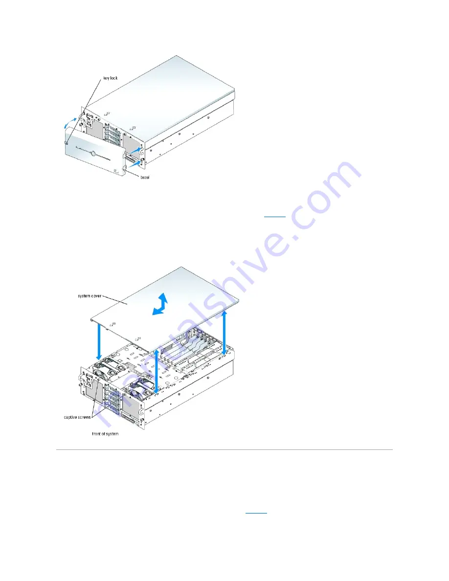
To remove the system cover, loosen the two captive screws at the front of the system. See 

Figure 5

-3

.  


4.

Slide the cover backward about 1.3 cm (0.5 inch), and grasp the cover on both sides.  


5.

Carefully lift the cover away from the system.  


Figure 5-3. Installing and Removing the System Cover 


Closing the System  


1.

Ensure that you did not leave tools or loose parts inside the system.  


2.

Place the cover over the sides of the chassis, and slide the cover forward.  


3.

Tighten the two captive screws at the front of the system to secure the cover. See 

Figure 5

-3

.  


4.

Reconnect the peripheral cables.  
 

Summary of Contents for PowerEdge 6850

Page 1: ...ell Inc is strictly forbidden Trademarks used in this text Dell the DELL logo PowerEdge PowerVault Dell OpenManage Dimension Inspiron OptiPlex Latitude Dell Precision PowerApp PowerConnect and DellNet are trademarks of Dell Inc Intel is a registered trademark and Xeon is a trademark of Intel Corporation Other trademarks and trade names may be used in this document to refer to either the entities c...

Page 2: ...s The wire connects the pins and creates a circuit To change a jumper setting pull the plug off its pin s and carefully fit it down onto the pin s indicated Figure A 1 shows an example of a jumper Figure A 1 Example Jumper A jumper is referred to as open or unjumpered when the plug is pushed down over only one pin or if there is no plug at all When the plug is pushed down over two pins the jumper ...

Page 3: ...n of the system board connectors Figure A 3 System Board Connectors Jumper Setting Description PASSWD default The password feature is enabled The password feature is disabled NVRAM_CLR default The configuration settings in NVRAM are retained at system boot The configuration settings in NVRAM are cleared at next system boot ...

Page 4: ...oltage regulator modules VRMs for processors 3 and 4 CPU 3 4 CACHE VRM Reserved FIBRE CHAN Integrated Fiber Channel module card MEM A B C D Memory riser card connector 4 NVRAM_CLR NVRAM jumper See Table A 1 PASSWD Password jumper See Table A 1 SCSI_A SCSI_B Connectors for the integrated SCSI controller 2 SLOT n Expansion slot connector 7 RAID_BAT Connector for the optional RAID battery RAID_DIMM C...

Page 5: ...n slots 6 and 7 if removed See Expansion Cards in Installing System Components 6 Close the system See Closing the System in Troubleshooting Your System 7 Reconnect the system to the electrical outlet and turn on the system The existing passwords are not disabled erased until the system boots with the password jumper plug on pins 2 and 3 However before you assign a new system and or setup password ...

Page 6: ...otection feature 12 Replace the expansion cards in expansion slots 6 and 7 if removed See Expansion Cards in Installing System Components 13 Close the system reconnect the system to the electrical outlet and turn on the system 14 Assign a new system and or setup password To assign a new password using the System Setup program see Using the System Setup Program in your User s Guide Back to Contents...

Page 7: ...iniature connector Serial Connector Autoconfiguration The default designation of the integrated serial connector is COM1 When you add an expansion card containing a serial connector that has the same designation as the integrated connector the system s autoconfiguration feature remaps reassigns the integrated serial connector to the next available designation Both the new and the remapped COM conn...

Page 8: ... Definition 1 DCD I Data carrier detect 2 SIN I Serial input 3 SOUT O Serial output 4 DTR O Data terminal ready 5 GND N A Signal ground 6 DSR I Data set ready 7 RTS O Request to send 8 CTS I Clear to send 9 RI I Ring indicator Shell N A N A Chassis ground NOTE Installing a video card automatically disables the system s integrated video controller Pin Signal I O Definition 1 RED O Red video 2 GREEN...

Page 9: ...tandard RJ45 compatible plug Observe the following cabling restrictions l Use Category 5 or greater wiring and connectors l Do not exceed a cable run length from a workstation to a hub of 100 m 328 ft For detailed guidelines on operation of a network see Systems Considerations of Multi Segment Networks in the IEEE 802 3 standard Back to Contents Page Pin Signal I O Definition 1 Vcc N A Supply volt...

Page 10: ...off the system and attached peripherals and disconnect the system from the electrical outlet 2 Open the system See Opening the System in Troubleshooting Your System 3 Remove fan 1 See Removing a System Fan in Installing System Components 4 Remove the three control panel securing screws from the system front panel See Figure C 1 5 Lift the control panel assembly out of the chassis 6 Disconnect the ...

Page 11: ...r out of the chassis See Figure 7 3 5 Remove fans 1 and 3 or 2 and 4 depending on which fan interposer board is being replaced See Removing a System Fan in Installing System Components CAUTION Many repairs may only be done by a certified service technician You should only perform troubleshooting and simple repairs as authorized in your product documentation or as directed by the online or telephon...

Page 12: ... to its electrical outlet and turn the system on including any attached peripherals SCSI Backplane Removing the SCSI Backplane 1 Turn off the system and attached peripherals and disconnect the system from the electrical outlet 2 Open the system See Opening the System in Troubleshooting Your System CAUTION Many repairs may only be done by a certified service technician You should only perform troub...

Page 13: ...he control panel cable from the control panel cable connector on the front of the SCSI backplane See Figure C 4 9 Remove the SCSI backplane a Pull the spring loaded blue retention pin away from the front of the backplane then slide the backplane upward See Figure C 4 b When the backplane cannot slide upward any farther pull the backplane toward the back of the system to remove it from the retentio...

Page 14: ... heat sinks on processors 2 and 4 See Installing a Processor in Installing System Components 5 Install the SCSI hard drives in their original locations See Installing a SCSI Hard Drive in Installing Drives 6 Install the optical drive diskette drive carrier Slide the drive carrier into its drive bay and press in the release latch See Figure 7 3 7 Install the cooling shroud See Installing the Coolin...

Page 15: ...alling a Non Hot Pluggable Memory Riser Card in Installing System Components 9 Remove the Fibre Channel module card if applicable See Removing a Fibre Channel Module Card in Installing System Components 10 Remove all expansion cards See Removing an Expansion Card in Installing System Components 11 Remove the expansion card insulator a Press in the two release tabs and lift up the front of the expa...

Page 16: ...the chassis intrusion switch cable and the RAID battery cable if applicable from the system board 14 Disconnect the power distribution cable harness from the system board The power distribution cable harness and the side of the chassis have Velcro pads to hold the cable harness in place while you remove the system board Bend the cable harness straight up and secure it to the side of the chassis Se...

Page 17: ...pring loaded blue retention pin located in the center of the system board and then slide the system board toward the front of the chassis until it stops See Figure C 9 b Slowly and evenly lift the system board above the retention hooks ensuring that the system board is clear of all 17 retention hooks then evenly lift up the left side of the system board See Figure C 9 c Lift the system board out o...

Page 18: ...CSI backplane respectively l Power distribution harness to the power connectors on the corner of the system board l Data interface cable from the system board BKPLN SIG connector to the SCSI backplane interface connector l SCSI power cable to the SCSI backplane power connector l RAID battery cable to the system board RAID BAT connector if applicable l Chassis intrusion switch cable to the system b...

Page 19: ...n Installing System Components 11 Install the cooling shroud See Installing the Cooling Shroud in Installing System Components 12 Install the optical drive diskette drive carrier Slide the drive carrier into its drive bay and press in the release latch See Figure 7 3 13 Install the SCSI hard drives in their original locations See Installing a SCSI Hard Drive in Installing Drives 14 Close the syste...

Page 20: ...ling Shroud in Installing System Components 4 Remove the heat sink or processor filler blank from processor 3 See Removing a Processor in Installing System Components 5 Remove the SCSI cables from the clip that is attached to the fan 3 air guard and move the cables to the side See Figure C 3 CAUTION Many repairs may only be done by a certified service technician You should only perform troubleshoo...

Page 21: ...n processor 3 See Installing a Processor in Installing System Components 4 Secure the SCSI cable s in the clip that is attached to the fan 3 air guard See Figure C 3 5 Install the cooling shroud See Installing the Cooling Shroud in Installing System Components 6 Close the system See Closing the System in Troubleshooting Your System 7 Reconnect the system to its electrical outlet and turn the syste...

Page 22: ...s Other Documents You May Need l The Rack Installation Guide or Rack Installation Instructions included with your rack solution describes how to install your system into a rack l The Getting Started Guide provides an overview of initially setting up your system l The User s Guide provides information about system features and technical specifications l Systems management software documentation des...

Page 23: ...cking system bezel incorporates a system status indicator The system status indicator lights blue when the system is operating correctly and lights amber when the system needs attention due to a problem with power supplies fans system temperature or hard drives Table 2 1 lists the system s indicator patterns Different patterns are displayed as events occur in the system Table 2 1 System Status Ind...

Page 24: ...lashes amber regardless of whether the system has been powered on Power on indicator power button The power on indicator lights when the system power is on The power on indicator blinks when power is available to the system but the system is not powered on The power button controls the DC power supply output to the system NOTE If you turn off the system using the power button and the system is run...

Page 25: ... drive is installed the drive being prepared for operation pattern appears followed by the drive online pattern Table 2 3 Hard Drive Indicator Patterns NOTE If a RAID controller is not present the green power on fault indicator is on if power is available to the drive The drive activity indicator also blinks when the drive is being accessed Condition Indicator Pattern Identify drive The green powe...

Page 26: ... system and the system is operational Off Indicates that no power is supplied to the system Blinking Indicates that power is supplied to the system but the system is in a standby state For information on standby states see your operating system documentation NOTE The 1470 W power supplies require 200 240 V to operate If they are plugged into 110 V electrical outlets the power supplies do not power...

Page 27: ...attery Replace the RAID battery See Activating the Optional Integrated RAID Controller in Installing Drives E0212 VOLT BATT CMOS Faulty system battery See Troubleshooting the System Battery in Troubleshooting Your System If the problem persists see Getting Help E0412 RPM FAN n FAN REDUNDANCY LOST Specified cooling fan is faulty improperly installed or missing See Troubleshooting System Cooling Pro...

Page 28: ...ndant memory Install a memory configuration that supports redundant memory spare bank feature See General Memory Module Installation Guidelines in Installing System Components Disable the Redundant Memory option in the System Setup program See Using the System Setup Program in your User s Guide Attempting to update Remote Configuration Please wait Remote Configuration is in progress Wait until the...

Page 29: ...mproperly installed Reinstall the operating system Keyboard controller failure Faulty keyboard controller faulty system board See Getting Help Keyboard data line failure Keyboard failure Keyboard stuck key failure Loose or improperly connected keyboard cable faulty keyboard faulty keyboard controller Ensure that the keyboard is properly connected If the problem persists replace the keyboard If the...

Page 30: ...e memory is configured to support this feature For more information see General Memory Module Installation Guidelines in Installing System Components and Using the System Setup Program in your User s Guide The amount of system memory has changed Faulty memory module Information only if you have changed the memory configuration See Troubleshooting System Memory in Troubleshooting Your System If the...

Page 31: ...e online or telephone service and support team Damage due to servicing that is not authorized by Dell is not covered by your warranty Read and follow the safety instructions that came with the product Code Cause Corrective Action 1 1 2 CPU register test failure See Troubleshooting the Microprocessors in Troubleshooting Your System 1 1 3 CMOS write read failure faulty system board Faulty system boa...

Page 32: ...see the documentation for the BMC and systems management applications Back to Contents Page 4 2 3 Gate A20 failure 4 2 4 Unexpected interrupt in protected mode See Troubleshooting Expansion Cards in Troubleshooting Your System 4 3 1 Improperly installed or faulty memory modules See Troubleshooting System Memory in Troubleshooting Your System 4 3 2 No memory modules installed in the first memory mo...

Page 33: ...e generated by system hardware or software Indicators Messages and Codes provides information about error messages that are hardware based If you receive an error message that is not listed see your operating system or software program documentation for troubleshooting information Input Errors Pressing a specific key or set of keys at the wrong time may produce unexpected results See the documenta...

Page 34: ...RQ4 Serial port 1 COM1 and COM3 IRQ5 Remote access controller IRQ6 Diskette drive controller IRQ7 Available IRQ8 Real time clock IRQ9 ACPI functions used for power management IRQ10 Available IRQ11 Available IRQ12 Available IRQ13 Math coprocessor IRQ14 IDE optical drive controller IRQ15 Available ...

Page 35: ...sequence of tests l Repeat tests l Display print or save test results l Temporarily suspend testing if an error is detected or terminate testing when a user defined error limit is reached l View help messages that briefly describe each test and its parameters l View status messages that inform you if tests are completed successfully l View error messages that inform you of problems encountered dur...

Page 36: ...er than its components selects all of the components of the device for testing Selecting Diagnostics Options Use the Diagnostics Options area to select how you want to test a device You can set the following options l Non Interactive Tests Only When checked runs only tests that require no user intervention l Quick Tests Only When checked runs only the quick tests on the device Extended tests will ...

Page 37: ...Back to Contents Page ...

Page 38: ...eshooting an Optical Drive Responding to a Systems Management Software Alert Message Troubleshooting a SCSI Tape Drive Inside the System Troubleshooting SCSI Hard Drives Opening the System Troubleshooting the Integrated RAID Controller Closing the System Troubleshooting a RAID Controller Card Troubleshooting a Wet System Troubleshooting Expansion Cards Troubleshooting a Damaged System Troubleshoot...

Page 39: ... Run the appropriate online diagnostic test See Using Server Administrator Diagnostics in Running System Diagnostics If the tests run successfully the problem is not related to video hardware See Finding Software Solutions If the tests fail see Getting Help Troubleshooting the Keyboard Problem l System message indicates a problem with the keyboard l Keyboard is not functioning properly Action 1 Ru...

Page 40: ...he System Setup Program in the User s Guide 2 If the problem is confined to a particular application see the application documentation for specific port configuration requirements that the program may require 3 Run the appropriate online diagnostic test See Using Server Administrator Diagnostics in Running System Diagnostics If the tests run successfully but the problem persists see the appropriat...

Page 41: ...etwork Action 1 Run the appropriate online diagnostic test See Using Server Administrator Diagnostics in Running System Diagnostics 2 Enter the System Setup program and confirm that the NICs are enabled See Using the System Setup Program in your User s Guide 3 Check the appropriate indicator on the NIC connector See NIC Indicator Codes in Indicators Messages and Codes l If the link indicator does ...

Page 42: ... Power is supplied to the system board and drives through one or two power supplies Opening the System The system is enclosed by an optional bezel and cover To upgrade or troubleshoot the system remove the bezel and cover to access the drives and internal system components 1 If applicable remove the bezel See Figure 5 2 a Unlock the keylock at the left end of the bezel b Rotate the left end of the...

Page 43: ...tem See Figure 5 3 4 Slide the cover backward about 1 3 cm 0 5 inch and grasp the cover on both sides 5 Carefully lift the cover away from the system Figure 5 3 Installing and Removing the System Cover Closing the System 1 Ensure that you did not leave tools or loose parts inside the system 2 Place the cover over the sides of the chassis and slide the cover forward 3 Tighten the two captive screws...

Page 44: ... system See Closing the System 9 Reconnect the system to the electrical outlet and turn on the system and peripherals If the system does not start properly see Getting Help 10 Run the appropriate online diagnostic test See Using Server Administrator Diagnostics in Running the System Diagnostics If the tests fail see Getting Help Troubleshooting a Damaged System Problem l System was dropped or dama...

Page 45: ... electrical outlet and turn on the system 4 Enter the System Setup program If the date and time are not correct in the System Setup program replace the battery See System Battery in Installing System Components If the problem is not resolved by replacing the battery see Getting Help Troubleshooting Power Supplies Problem l System status indicator is amber l Power supply fault indicator is amber Ac...

Page 46: ...ed peripherals 8 If the problem is not resolved install a new fan See Fans in Installing System Components 9 If the replacement fan does not operate see Getting Help Troubleshooting System Memory Problem l Faulty memory riser card l Faulty memory module l Faulty system board l System status indicator is amber l LCD error code or system beep code indicates a memory problem NOTICE The power supplies...

Page 47: ...stem and attached peripherals and disconnect the system from its electrical outlet b Open the system See Opening the System c Repeat step d through step h in step 6 for each memory module installed 8 If you have tested all the memory modules and the problem persists or none of the memory modules passes the system board is faulty See Getting Help The system starts up successfully but there are memo...

Page 48: ...the system from the electrical outlet 4 Remove the diskette optical drive carrier and ensure that the diskette drive cable is securely attached Reinstall the diskette optical drive carrier making sure it is fully inserted and properly seated in the system chassis See Figure 7 3 5 Reconnect the system to the electrical outlet and turn on the system and attached peripherals 6 Run the appropriate onl...

Page 49: ...ystem Setup Program in the User s Guide 4 Run the appropriate online diagnostic test See Using Server Administrator Diagnostics in Running System Diagnostics 5 Turn off the system and attached peripherals and disconnect the system from the electrical outlet 6 Remove the diskette optical drive carrier and ensure that the optical drive cable is securely attached Reinstall the diskette optical drive ...

Page 50: ...cable connection to the system board 12 Close the system See Closing the System 13 Reconnect the system to the electrical outlet and turn on the system including attached peripherals 14 If the problem is not resolved see the documentation for the tape drive for additional troubleshooting instructions 15 If you cannot resolve the problem see Getting Help Troubleshooting SCSI Hard Drives Problem l D...

Page 51: ...the files to the drive If the problem persists see Getting Help Troubleshooting the Integrated RAID Controller Problem l Error message indicates a problem with the optional integrated RAID controller Action 1 Run the appropriate online diagnostic test See Using Server Administrator Diagnostics in Running System Diagnostics 2 Enter the System Setup program and ensure that the Embedded RAID Controll...

Page 52: ... Components 5 Ensure that the appropriate cables are firmly connected to their corresponding connectors on the controller card and SCSI backplane 6 Close the system See Closing the System 7 Reconnect the system to the electrical outlet and turn on the system and attached peripherals If the problem persists see the RAID controller s documentation for more information on troubleshooting Troubleshoot...

Page 53: ... see Getting Help 13 For each expansion card you removed in step 9 perform the following steps a Turn off the system and attached peripherals and disconnect the system from the electrical outlet b Open the system See Opening the System c Reinstall one of the expansion cards See Installing an Expansion Card d Close the system See Closing the System e Run the appropriate diagnostic test If the tests...

Page 54: ...ocate the processors see Figure A 3 If only one processor is installed see Getting Help 12 Close the system See Closing the System 13 Reconnect the system to the electrical outlet and turn on the system and attached peripherals 14 Run the appropriate online diagnostic test If the tests complete successfully go to step 20 15 Turn off the system and attached peripherals and disconnect the system fro...

Page 55: ...in Troubleshooting Your System 4 Remove the memory riser cards A and B See Removing and Installing a Non Hot Pluggable Memory Riser Card 5 Remove the system battery See Figure A 3 for the battery connector location on the system board a Support the battery connector by pressing down firmly on the positive side of the connector See Figure 6 1 b While supporting the battery connector press the batte...

Page 56: ...ram to confirm that the battery operates properly 11 From the main screen select System Time to enter the correct time and date 12 Re enter any system configuration information that is no longer displayed on the System Setup screens and then exit the System Setup program 13 To test the newly installed battery see Troubleshooting the System Battery in Troubleshooting Your System Fans The system s f...

Page 57: ...ing the Cooling Shroud CAUTION Many repairs may only be done by a certified service technician You should only perform troubleshooting and simple repairs as authorized in your product documentation or as directed by the online or telephone service and support team Damage due to servicing that is not authorized by Dell is not covered by your warranty Read and follow the safety instructions that cam...

Page 58: ...ower supply out of the chassis See Figure 6 5 Figure 6 5 Installing and Removing a Power Supply NOTE The 1470 W power supplies require 200 240 V to operate If they are plugged into 110 V electrical outlets the power supplies do not power up NOTICE The system is in the redundant mode when two power supplies are installed and both power supplies are connected to an AC power source Remove and replace...

Page 59: ...h PCI Express expansion slot Slot 2 is a hot plug 3 3 V 64 bit 133 MHz PCI X expansion slot Slots 3 through 5 are hot plug x4 lane width PCI Express expansion slots Slots 6 and 7 are non hot plug 3 3 V 64 bit 100 MHz PCI X expansion slots Figure 6 6 Expansion Slots NOTE If you unlatched the cable management arm in step 3 of the previous procedure relatch it For information about the cable manageme...

Page 60: ...void damage to the expansion card or system board refer to the expansion slot indicator when you add or remove a PCI Express expansion card Green Power Indicator Amber Attention Indicator Safe to Add Remove Card Description Off Off Yes Connector power is off On Off No Connector power is on Flash Off No Connector is being powered up or powered down Off On Yes Fault On Flash No Slot is being identif...

Page 61: ...f See Figure 6 8 and Table 6 1 Figure 6 8 Installing and Removing Hot Plug Expansion Cards NOTE Keep this bracket if you need to remove the expansion card Filler brackets must be installed over empty expansion card slots to maintain Federal Communications Commission FCC certification of the system The brackets also keep dust and dirt out of the system and aid in proper cooling and airflow inside t...

Page 62: ...4 Open the expansion card retainer adjacent to the slot See Figure 6 7 5 Grasp the expansion card and carefully remove it from the system board connector 6 If you are permanently removing the card replace the metal filler bracket over the empty card slot opening NOTICE Be very careful when removing the bracket to avoid dropping it onto the system board and damaging the system board NOTE Keep this ...

Page 63: ...rm the following steps 1 Turn off the system and attached peripherals and disconnect the system from the electrical outlet 2 Open the system See Opening the System in Troubleshooting Your System 3 Remove memory risers cards C and D See Removing and Installing a Non Hot Pluggable Memory Riser Card 4 Open the plastic Fibre Channel module card retainer adjacent to the back of the empty slot See Figur...

Page 64: ...removing the card replace the metal filler bracket over the empty card slot opening NOTE Keep this bracket if you need to remove the Fibre Channel module card Filler brackets must be installed over empty card slots to maintain Federal Communications Commission FCC certification of the system The brackets also keep dust and dirt out of the system and aid in proper cooling and airflow inside the sys...

Page 65: ...es l If you install both single ranked and dual ranked memory modules the dual ranked memory modules must be installed in bank 1 Removing a Memory Riser Card Filler Blank If you are adding an additional memory riser card you will need to remove the filler blank installed in the location you are adding the new riser card The filler blanks are installed to direct cooling airflow if a memory riser is...

Page 66: ...are a mirror pair Mirroring must be enabled in the System Setup program Table 6 2 and Table 6 3 show examples of different memory configurations Table 6 3 lists the various allowable combinations of single and dual ranked memory modules Table 6 2 Sample Memory Configurations per Memory Riser Card Table 6 3 Allowable Memory Module Configurations Single Ranked and Dual Ranked Memory Modules NOTE Spa...

Page 67: ...ing Memory Modules 7 Install the memory riser card a Ensure that the riser card handle is fully extended and then align both edges of the riser card with the front and rear riser card guides See Figure 6 13 b Lower the riser card until the riser card connector is near the riser card connector on the system board c Ensure that both connectors are properly aligned and then gently press the riser car...

Page 68: ... and the RAID memory riser card configuration is redundant The memory riser card is hot pluggable in RAID mode The indicator turns off if a memory riser card in the RAID configuration becomes disabled and is no longer redundant Attention indicator This indicator is amber and the green power indicator is off if the memory riser card contains a faulty memory module or if a recovery error occurs whil...

Page 69: ...d 2 Locate the memory module sockets See Figure A 3 3 Press the ejectors on the memory module socket down and out as shown in Figure 6 14 to allow the memory module to be inserted into the socket Figure 6 14 Installing and Removing a Memory Module 4 Align the memory module s edge connector with the alignment key on the memory module socket and insert the memory module in the socket 5 Press down on...

Page 70: ...cessors Each processor and its associated internal cache memory are contained in a pin grid array PGA package that is installed in a ZIF socket on the system board Removing a Processor 1 Turn off the system and attached peripherals and disconnect the system from the electrical outlet 2 Open the system See Opening the System in Troubleshooting Your System 3 Remove the cooling shroud See Removing th...

Page 71: ... system See Opening the System in Troubleshooting Your System 3 Remove the cooling shroud See Removing the Cooling Shroud NOTICE If you are going to reinstall the same processor and heat sink ensure that you do not disturb the thermal grease on either the processor or the heat sink NOTICE If you are removing processor 1 or processor 3 pull upward on the blue plastic tab next to the socket to open ...

Page 72: ...elease lever back down until it snaps into place securing the processor 8 Install the heat sink a Using a clean lint free cloth remove the existing thermal grease from the heat sink b Apply thermal grease evenly to the top of the processor c Place the heat sink onto the processor See Figure 6 15 d Squeeze the sides of the heat sink retention clip together and press down on the blue tab When the lo...

Page 73: ...own in Figure 6 18 to allow the VRM to be inserted into the socket Figure 6 18 Installing a VRM 5 Align the VRM s edge connector with the alignment key on the socket and insert the VRM in the socket See Figure 6 18 6 Press down on the VRM with your thumbs while pulling up on the ejectors with your index fingers to lock the VRM into the socket 7 Close the system See Closing the System in Troublesho...

Page 74: ...s than those provided with the operating system to partition and format SCSI hard drives When you format a high capacity SCSI hard drive allow enough time for the formatting to be completed Long format times for these drives are normal A 9 GB hard drive for example can take up to 2 5 hours to format Installing a SCSI Hard Drive 1 If the system does not have an optional RAID controller card or opti...

Page 75: ...il it is free of the drive bay 6 Replace the front bezel if it was removed in step 2 Installing a Diskette Drive 1 Turn off the system including any attached peripherals and disconnect the system from the electrical outlet 2 Remove the front bezel if attached See Opening the System in Troubleshooting Your System 3 To remove the drive carrier pull the release latch forward then slide the carrier ou...

Page 76: ...the latch c Lift the optical drive or optical drive filler plate from the carrier Figure 7 4 Installing a Diskette Drive in the Drive Carrier 5 To remove the diskette drive filler plate pull the retention spring slightly away from the filler plate then lift the filler plate from the carrier 6 Deflect the retention spring slightly then insert the diskette drive into the carrier ...

Page 77: ...the thumbscrew from the latch securing the optical drive or filler plate See Figure 7 5 b Remove the latch c Lift the optical drive filler plate from the carrier Figure 7 5 Installing an Optical Drive in the Drive Carrier 5 Install the new optical drive in the carrier See Figure 7 5 The pins on the carrier fit into the corresponding holes in the side of the drive 6 Attach the interface board to th...

Page 78: ...pansion Card in Installing System Components 7 Connect the tape drive s SCSI interface cable to the drive 8 Connect the other end of the SCSI interface cable to the SCSI controller card or the external SCSI connector on the system s back panel see Figure 2 2 9 Connect the tape drive s power cable to an electrical outlet 10 Close the system See Closing the System in Troubleshooting Your System 11 R...

Page 79: ...lane toward the back of the system to remove it from the retention hooks c Lift the board out of the system being careful to avoid damaging components on the face of the board d Place the SCSI backplane face down on a work surface Figure 7 6 Removing and Installing the SCSI Backplane Installing the SCSI Daughter Card 1 Hold the daughter card by its edges with the card connector facing the SCSI bac...

Page 80: ...place the cover See Closing the System 9 Reconnect the system to its electrical outlet and turn the system on including any attached peripherals 10 If applicable reattach the bezel Activating the Optional Integrated RAID Controller This subsection explains how to activate your system s integrated RAID controller 1 Turn off the system including any attached peripherals and disconnect the system fro...

Page 81: ...he battery holder See Figure 7 8 10 Connect the battery power cable to the RAID battery cable connector on the system board See Figure A 4 11 Replace the memory filler blank or the memory riser card in memory slot C See Removing and Installing a Non Hot Pluggable Memory Riser Card 12 Replace the cover See Closing the System 13 Reconnect the system to its electrical outlet and turn the system on in...

Page 82: ...ane see Figure A 5 Drive 0 functions as the boot drive 2 3 Split Backplane Configurations l To use the optional integrated ROMB controller in a split 2 3 backplane configuration Connect SCSI channel A on the system board see Figure A 3 to connector SCSI A on the SCSI backplane see Figure A 5 This channel controls the boot drive drive 0 and drives 1 and 2 Connect SCSI channel B on the system board ...

Page 83: ...ll countries When prompted by Dell s automated telephone system enter your Express Service Code to route the call directly to the proper support personnel If you do not have an Express Service Code open the Dell Accessories folder double click the Express Service Code icon and follow the directions For instructions on using the technical support service see Technical Support Service and Before You...

Page 84: ...stics to provide fast accurate answers To contact Dell s technical support service see Before You Call and then see the contact information for your region Dell Enterprise Training and Certification Dell Enterprise Training and Certification is available see www dell com training for more information This service may not be offered in all locations Problems With Your Order If you have a problem wi...

Page 85: ... access the following websites l www dell com l support dell com technical support l premiersupport dell com technical support for educational government healthcare and medium large business customers including Premier Platinum and Gold customers For specific web addresses for your country find the appropriate country section in the table below NOTE Toll free numbers are for use within the country...

Page 86: ...Access Code 900 Country Code 43 City Code 1 Website support euro dell com E mail tech_support_central_europe dell com Home Small Business Sales 0820 240 530 00 Home Small Business Fax 0820 240 530 49 Home Small Business Customer Care 0820 240 530 14 Preferred Accounts Corporate Customer Care 0820 240 530 16 Home Small Business Technical Support 0820 240 530 14 Preferred Accounts Corporate Technica...

Page 87: ... Division toll free 800 858 2557 Large Corporate Accounts GCP toll free 800 858 2055 Large Corporate Accounts Key Accounts toll free 800 858 2628 Large Corporate Accounts North toll free 800 858 2999 Large Corporate Accounts North Government and Education toll free 800 858 2955 Large Corporate Accounts East toll free 800 858 2020 Large Corporate Accounts East Government and Education toll free 800...

Page 88: ...tomer Care 06103 766 9420 Large Accounts Customer Care 06103 766 9560 Public Accounts Customer Care 06103 766 9555 Switchboard 06103 766 7000 Greece International Access Code 00 Country Code 30 Website support euro dell com E mail support euro dell com gr en emaildell Technical Support 00800 44 14 95 18 Gold Service Technical Support 00800 44 14 00 83 Switchboard 2108129810 Gold Service Switchboar...

Page 89: ...chnical Support Dell Precision OptiPlex and Latitude toll free 0120 198 433 Technical Support outside of Japan Dell Precision OptiPlex and Latitude 81 44 556 3894 Technical Support PDAs projectors printers routers toll free 0120 981 690 Technical Support outside of Japan PDAs projectors printers routers 81 44 556 3468 Faxbox Service 044 556 3490 24 Hour Automated Order Service 044 556 3801 Custome...

Page 90: ...882 1519 Netherlands Amsterdam International Access Code 00 Country Code 31 City Code 20 Website support euro dell com Technical Support 020 674 45 00 Technical Support Fax 020 674 47 66 Home Small Business Customer Care 020 674 42 00 Relational Customer Care 020 674 4325 Home Small Business Sales 020 674 55 00 Relational Sales 020 674 50 00 Home Small Business Sales Fax 020 674 47 75 Relational S...

Page 91: ... Website support euro dell com E mail czech_dell dell com Technical Support 02 5441 5727 Customer Care 420 22537 2707 Fax 02 5441 8328 Tech Fax 02 5441 8328 Switchboard Sales 02 5441 7585 South Africa Johannesburg International Access Code 09 091 Country Code 27 City Code 11 Website support euro dell com E mail dell_za_support dell com Gold Queue 011 709 7713 Technical Support 011 709 7710 Custome...

Page 92: ...ebsite support euro dell com Customer Care website support euro dell com uk en ECare Form Home asp E mail dell_direct_support dell com Technical Support Corporate Preferred Accounts PAD 1000 employees 0870 908 0500 Technical Support direct and general 0870 908 0800 Global Accounts Customer Care 01344 373 186 Home and Small Business Customer Care 0870 906 0010 Corporate Customer Care 01344 373 185 ...

Page 93: ...ore Dell refurbished computers toll free 1 888 798 7561 Software and Peripherals Sales toll free 1 800 671 3355 Spare Parts Sales toll free 1 800 357 3355 Extended Service and Warranty Sales toll free 1 800 247 4618 Fax toll free 1 800 727 8320 Dell Services for the Deaf Hard of Hearing or Speech Impaired toll free 1 877 DELLTTY 1 877 335 5889 U S Virgin Islands General Support 1 877 673 3355 Vene...

Page 94: ...x Latitude Dell Precision PowerApp PowerConnect and DellNet are trademarks of Dell Inc Intel is a registered trademark and Xeon is a trademark of Intel Corporation Other trademarks and trade names may be used in this document to refer to either the entities claiming the marks and names or their products Dell Inc disclaims any proprietary interest in trademarks and trade names other than its own De...

Reviews: