background image

Internal Views


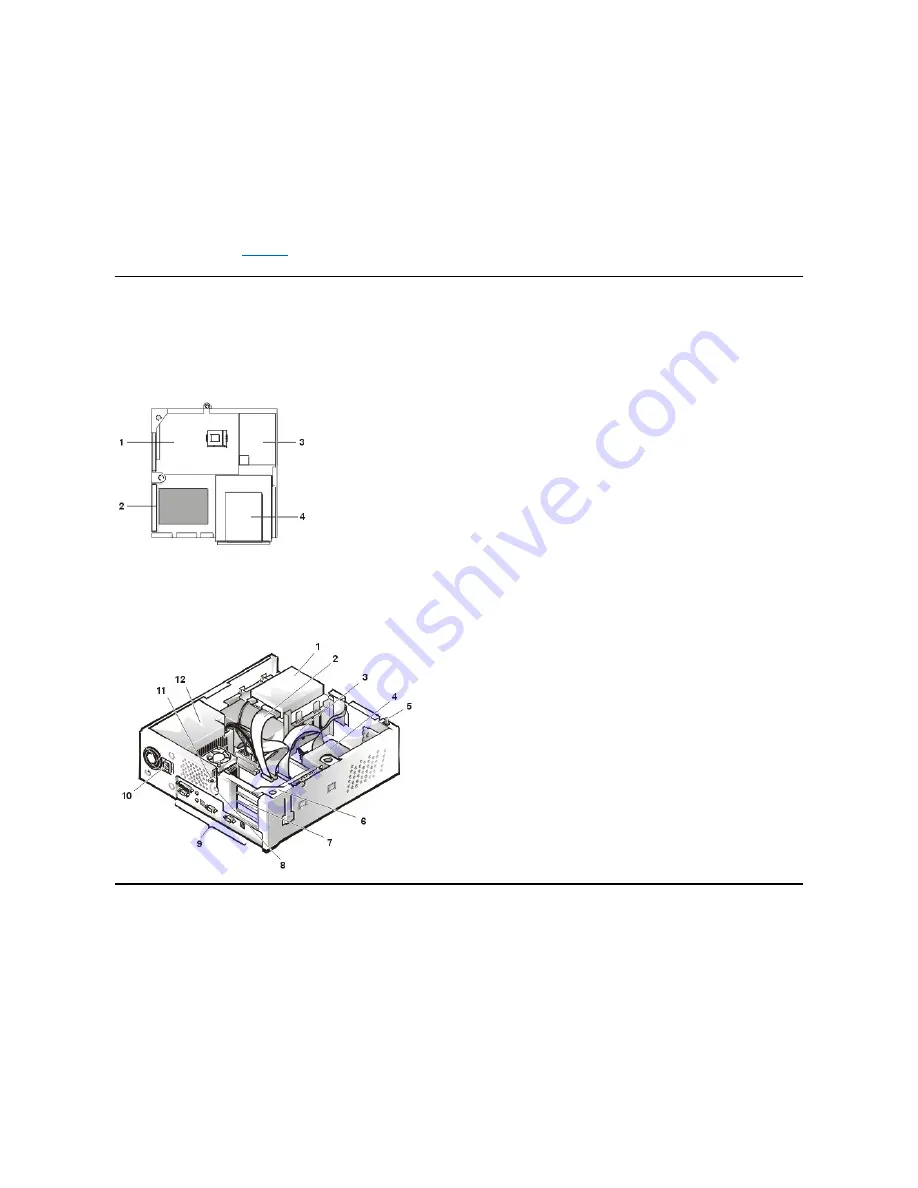
Figure 1 shows a top view of the low-profile chassis to help you orient yourself when you work inside the computer.


Figure 1. Low-Profile Chassis Orientation View


Figure 2 shows the low-profile chassis with the cover removed.


Figure 2. Inside the Low-Profile Chassis


Computer Cover 

Figure 3. Computer Cover Removal


3. If you are disconnecting a peripheral from the computer or are removing a component from the system board, wait 10 to 20 seconds 

after disconnecting the computer from AC power before disconnecting the peripheral or removing the component to avoid possible 
damage to the system board. 
 

4. Wear a wrist grounding strap, and clip it to an unpainted metal surface, such as the padlock loop on the back of the chassis. If a wrist 

grounding strap is not available, touch any unpainted metal surface on the back of the computer or on the computer chassis, such as 

the power supply, to discharge any static charge from your body before touching anything inside the computer.  While you work, 

periodically touch an unpainted metal surface on the computer chassis to dissipate any static electricity that might harm internal 
components. Also avoid touching components or contacts on a card and avoid touching pins on a chip. 
 

5. Verify that the auxiliary power indicator on the system board is not on. If it is on, you may need to wait 10 to 30 seconds for it to go out 

(see Item 13 on 

Figure 17

). 


1

System board

2

Hard-disk drive

3

Power supply

4

Externally accessible drive bays

1

Diskette drive in upper bay

2

Diskette drive interface cable

3

Hard-disk drive interface cable

4

Hard-disk drive

5

Chassis intrusion switch

6

Expansion-card cage

7

Expansion-card slots

8

Security cable slot

9

I/O ports and connectors

10

AC power receptacle

11

Padlock ring

12

Power supply

Summary of Contents for OptiPlex GX100

Page 1: ... you how to avoid the problem CAUTION A CAUTION indicates a potentially hazardous situation which if not avoided may result in minor or moderate injury Information in this document is subject to change without notice 1999 2000 Dell Computer Corporation All rights reserved Reproduction in any manner whatsoever without the written permission of Dell Computer Corporation is strictly forbidden Tradema...

Page 2: ...t driver Also use a wrist grounding strap as explained in Precautionary Measures Precautionary Measures Before you perform any procedure in this section take a few moments to read the following caution for your personal safety and to prevent damage to the system from ESD Overview Recommended Tools Precautionary Measures Internal Views Computer Cover Eject Power and Reset Buttons Front Panel Insert...

Page 3: ...h any unpainted metal surface on the back of the computer or on the computer chassis such as the power supply to discharge any static charge from your body before touching anything inside the computer While you work periodically touch an unpainted metal surface on the computer chassis to dissipate any static electricity that might harm internal components Also avoid touching components or contacts...

Page 4: ... Figure 4 Computer Cover Replacement To replace the low profile chassis computer cover perform the following steps 1 Face the front of the computer and hold the cover at a slight angle see Figure 4 2 Align the bottom of the cover with the bottom of the chassis and insert the hooks on the cover into the recessed slots on the computer chassis so that the tabs catch the hooks inside the slots 3 Pivot...

Page 5: ...nel Inserts Figure 6 5 25 Inch Front Panel Insert Removal To remove a 5 25 inch front panel insert perform the following steps 1 Hold the bezel with the front facing you 2 From the front of the top cover use your thumbs to press inward on the insert until it snaps free of the cover To replace a 5 25 inch front panel insert position the two ring tabs over the posts on the inside of the bay opening ...

Page 6: ...e chassis perform the following steps 1 Disconnect the chassis intrusion switch cable connector from the control panel on the front of the chassis and shown in Figure 8 Note the routing of the chassis intrusion cable as you remove it from the chassis Hooks on the chassis keep the cable in place 2 Slide the chassis intrusion switch out of its slot to remove it from the chassis see Figure 8 3 Instal...

Page 7: ... hard disk drive bracket assembly perform the following steps 1 Disconnect the DC power cable and EIDE cable from the drive 2 Loosen the captive screw securing the hard disk drive bracket to the bottom of the chassis 3 Grasp the drive bracket and pivot it upward from the chassis until the two hinge tabs located on the side opposite the screw clear the floor divider see Figure 10 Then lift the brac...

Page 8: ... 7 Connect a power cable to the power input connector on the back of the drive see Figure 12 8 Check all connectors to ensure that they are properly cabled and firmly seated 9 Connect one of the device connectors on the EIDE cable to the 40 pin interface connector on the back of the hard disk drive NOTICE You must match the red colored stripe on the EIDE cable with pin 1 on the drive s interface c...

Page 9: ...ocumentation that came with your operating system System Power Supply Figure 13 Power Supply Removal To remove the system power supply perform the following steps 1 Disconnect the AC power cable from the back of the power supply 2 Disconnect the DC power cables from the system board and the drives Note the routing of the DC power cables underneath the tabs in the chassis as you remove them from th...

Page 10: ... the expansion card cage see Figure 14 Slide the expansion card cage into place 2 Rotate the securing lever downward until it is flush with the top of the chassis Make sure that the riser board is fully seated in the RISER connector on the system board 3 Reconnect any cables you removed in step 1 of the previous procedure Riser Boards The low profile chassis is available with either a PCI riser bo...

Page 11: ...ED 2 ISA expansion slot 1 ISA1 shared with PCI2 3 ISA expansion slot 2 ISA2 4 Remote Wakeup header WOL 5 PCI expansion slot 1 PCI1 6 PCI expansion slot 2 PCI2 shared with ISA1 CAUTION Ground yourself by touching an unpainted metal surface on the back of the computer NOTICE Use a wrist grounding strap as explained in Precautionary Measures 1 NIC connector 2 Video connector 3 Fan power connector 4 S...

Page 12: ...els for connectors and sockets on your system board and it gives a brief description of their functions Table 1 System Board Connectors and Sockets Expansion Cards The low profile GX100 chassis can accommodate three 32 bit PCI expansion cards Figure 19 shows an example of a 32 bit PCI expansion card Figure 19 32 Bit PCI Expansion Card Example Connector or Socket Description AUX_LED Auxiliary power...

Page 13: ...xpansion card for installation and remove the computer cover CAUTION Use a wrist grounding strap as explained in Precautionary Measures NOTE Installing filler brackets over empty card slot openings is necessary to maintain Federal Communications Commission FCC certification of the system The brackets also keep dust and dirt out of your computer NOTE After you remove and replace the cover the chass...

Page 14: ... information about the card s cable connections 6 Replace the computer cover and reconnect your computer and peripherals to their power sources and turn them on 7 To reset the chassis intrusion detector enter System Setup and reset Chassis Intrusion to Enabled or Enabled Silent See the User s Guide for detailed information on the chassis intrusion detector DIMMs Figure 22 DIMM Removal To remove a ...

Page 15: ...ertion force ZIF socket with a lever type handle that secures the chip in or releases it from the socket To remove the chip pull the microprocessor socket release lever straight out until the chip is released see Figure 25 Then remove the chip from the socket Leave the release lever extended so that the socket is ready for the new microprocessor Figure 25 Microprocessor Chip Removal 1 Ejectors 2 2...

Page 16: ...roprocessor socket release lever back toward the socket until it snaps into place securing the chip Figure 26 Microprocessor Chip Installation 11 Unpack the heat sink included in your upgrade kit Peel the release liner from the adhesive tape that is attached to the bottom of the heat sink 12 Place the heat sink on top of the microprocessor chip see Figure 27 Figure 27 Heat Sink Installation 1 Micr...

Page 17: ...ntifies the installed microprocessor 17 Run the Dell Diagnostics to verify that the new microprocessor is operating correctly System Battery Figure 28 System Battery Removal To remove the system battery perform the following steps 1 If possible enter System Setup and print the System Setup screens 2 Remove the system battery by carefully prying it out of its socket with your fingers or with a blun...

Page 18: ...t the system board out of the chassis be sure to lift evenly and not twist the system board To replace the system board perform the following steps 1 Remove the DIMMs and the microprocessor heat sink assembly and install them on the replacement board 2 Set the jumpers on the new system board so that they are identical to those on the old board unless you are installing a microprocessor upgrade 3 P...

Page 19: ...lso use a wrist grounding strap as explained in Precautionary Measures Precautionary Measures Before you perform any of the procedures in this file take a few moments to read the following caution for your personal safety and to prevent damage to the system from ESD Overview Recommended Tools Precautionary Measures Internal Views Computer Cover Front Bezel Eject Power and Reset Buttons Front Panel...

Page 20: ...d metal surface on the back of the computer or on the computer chassis such as the power supply to discharge any static charge from your body before touching anything inside the computer While you work periodically touch an unpainted metal surface on the computer chassis to dissipate any static electricity that might harm internal components Also avoid touching components or contacts on a card and...

Page 21: ...r away Figure 4 Computer Cover Replacement To replace the mini tower computer cover perform the following steps 1 Face the left side of the computer and hold the cover at a slight angle as shown in Figure 4 2 Align the top of the cover with the top of the chassis and insert the hooks on the cover into the recessed slots on the computer chassis so that the tabs catch the hooks inside the slots 3 Pi...

Page 22: ...the chassis snap into their slots on the bezel Eject Power and Reset Buttons Figure 6 Eject Power and Reset Button Removal To remove the eject power and reset buttons perform the following steps 1 Lay the front bezel on a flat work surface with the back of the bezel facing up 2 To remove the 3 5 inch diskette eject button pull gently on the plastic part of the button until it comes free 3 To remov...

Page 23: ...el Figure 8 Control Panel Removal To remove the control panel perform the following steps 1 Disconnect the control panel cable from the control panel connector on the system board see System Board Labels for the location of the PANEL connector Note the routing of the control panel cable as you remove it from the chassis 2 Disconnect the the chassis intrusion switch cable connector from the control...

Page 24: ...g of the chassis intrusion cable as you remove the cable from the chassis Chassis hooks may hold the cable in place inside the chassis 3 Slide the chassis intrusion switch out of its slot on the chassis and carefully remove the switch and its attached cable from the chassis 4 Install the replacement chassis intrusion switch and cable 5 To reset the chassis intrusion detector enter System Setup and...

Page 25: ...ve bracket out of the chassis 3 Remove the drive mounting screw from the left side of the drive and remove the drive from the bracket to the bottom of the bracket see Figure 11 When you replace the 3 5 inch diskette drive be sure that the two hooks on the right side of the bracket engage the mounting holes in the side of the 3 5 inch diskette drive 5 25 Inch Drive Figure 12 Removing a 5 25 Inch Dr...

Page 26: ... screws in the order stamped on the bottom of the bracket 4 Check the alignment of the computer cover around the 5 25 inch bezel Adjust the drive forward or backward on the bracket to align it 5 To ensure proper installation align all screw holes and ensure that the tabs on the front of the bracket are flush with the front of the drive see Figure 13 Figure 13 Attaching the Drive Bracket to the New...

Page 27: ...iate EIDE interface cable to the EIDE interface connector on the back of the drive see Figure 15 If your system came with an EIDE CD ROM or tape drive use the spare connector on the existing interface cable Otherwise use the EIDE interface cable provided in the drive kit Hard Disk Drive Removal Figure 16 Hard Disk Drive Bracket Removal 1 5 25 inch drive 1 DC power cable 2 EIDE interface connector ...

Page 28: ...e computer NOTICE When you unpack the drive do not set it on a hard surface which may damage the drive Instead set the drive on a surface such as a foam pad that will sufficiently cushion it 1 Prepare the drive for installation Check the documentation for the drive to verify that it is configured for your computer system 2 If not already done remove the computer cover 3 If not already done remove ...

Page 29: ...red stripe on the EIDE cable with pin 1 on the drive s interface connector to avoid possible damage to your system 8 Connect the cable connector on the EIDE cable to the 40 pin interface connector on the back of the hard disk drive Figure 19 Hard Disk Drive Cables Attachment NOTICE You must match the blue connector on the interface cable to the EIDE1 connector on the system board to avoid possible...

Page 30: ...otate it upward until it locks 3 Disconnect the DC power cables from the system board and the drives Note the routing of the DC power cables underneath the tabs in the chassis as you remove them from the system board and drives It is important to route these cables properly when you replace them to prevent them from being pinched or crimped 4 Remove the screw above the AC power receptacle 5 Lift u...

Page 31: ...nsion card cage see Figure 21 Slide the expansion card cage into place 2 Rotate the securing lever downward until it is flush with the top side of the chassis Make sure that the riser board is fully seated in the RISER connector on the system board see Figure 22 3 Reconnect any cables you removed in step 1 of the previous procedure Riser Boards The mini tower chassis is available with either a PCI...

Page 32: ...n slot 1 PCI1 2 PCI expansion slot 2 PCI2 3 PCI expansion slot 3 PCI3 4 PCI expansion slot 4 PCI4 shared with ISA1 5 ISA expansion slot 1 ISA1 shared with PCI4 6 Standby power indicator LED AUX_LED 7 ISA expansion slot 4 ISA4 8 ISA expansion slot 3 ISA3 9 ISA expansion slot 2 ISA2 shared with PCI5 10 PCI expansion slot 5 PCI5 shared with ISA2 11 Remote Wakeup header WOL CAUTION Use a wrist groundi...

Page 33: ... 1 lists the labels for connectors and sockets on your system board and gives a brief description of their functions Table 1 System Board Connectors and Sockets Expansion Cards The mini tower GX100 chassis can accommodate up to five 32 bit PCI expansion cards Figure 26 shows an example of a 32 bit PCI expansion card Figure 26 32 Bit PCI Expansion Card Example Connector or Socket Description AUX_LE...

Page 34: ...tructions on the Intrusion detector Expansion Card Installation Figure 27 Expansion Card Installation CAUTION Use a wrist grounding strap as explained in Precautionary Measures NOTE Installing filler brackets over empty card slot openings is necessary to maintain Federal Communications Commission FCC certification of the system The brackets also keep dust and dirt out of your computer NOTE After y...

Page 35: ...w you removed in step 2 5 Connect any cables that should be attached to the card See the documentation provided with the card for information about the card s cable connections 6 Replace the computer cover and reconnect your computer and peripherals to their power sources and turn them on 7 To reset the chassis intrusion detector enter System Setup and reset Chassis Intrusion to Enabled or Enabled...

Page 36: ... computer cover 2 Locate the microprocessor socket on the system board 3 Remove the fan power cable from its connector on the system board Then remove two screws securing the fan to the heat sink assembly and remove the fan 4 Remove the metal clip that secures the heat sink to the microprocessor socket Then remove the heat sink from the microprocessor chip 1 Ejectors 2 2 Notches 2 1 Securing clip ...

Page 37: ...chip in the socket see Figure 33 If the release lever on the microprocessor socket is not all the way out move it to that position now With the pin 1 corners of the chip and socket aligned align the pins on the chip with the holes in the socket Set the chip lightly in the socket NOTICE Be careful not to bend any of the pins when removing the microprocessor from its socket Bending the pins can perm...

Page 38: ... 34 and hook the unfolded end of the clip over the tab on the top edge of the socket Then press down on the folded end of the clip to snap the clip over the tab on the bottom edge of the socket 13 Replace the fan assembly and secure it with two thumbscrews 14 Install the microprocessor fan cable connector to the FAN connector on the system board 15 Replace the computer cover and then reconnect you...

Page 39: ...hat secures the system board to the bottom of the chassis 7 Slide the system board toward the front of the chassis until it stops 8 Carefully lift the system board out of the chassis be sure to lift evenly and not twist the system board If you are replacing a system board remove the DIMMs and the microprocessor heat sink assembly and install them on the replacement board Also set the jumpers on th...

Page 40: ...board Back to Contents Page ...

Page 41: ...re you perform any procedures in this manual take a few moments to read the following caution for your personal safety and to prevent damage to the system from ESD Overview Recommended Tools Precautionary Measures Internal Views Computer Cover Eject and Power Buttons Control Panel Chassis Intrusion Switch Drives System Power Supply Riser Board System Board Components Expansion Card Cage Expansion ...

Page 42: ... anything inside the computer While you work periodically touch an unpainted metal surface on the computer chassis to dissipate any static electricity that might harm internal components Also avoid touching components or contacts on a card and avoid touching pins on a chip 5 Verify that the auxiliary power indicator on the system board is not on If it is on you may need to wait 10 to 30 seconds fo...

Page 43: ...mputer Cover Replacement To replace the computer cover perform the following steps 1 Face the front of the computer and hold the cover at a slight angle see Figure 4 2 Align the bottom of the cover with the bottom of the chassis and insert the hooks on the cover into the recessed slots on the computer chassis so that the tabs catch the hooks inside the slots 3 Pivot the cover down toward the back ...

Page 44: ...e the power supply 3 Disconnect the control panel cable from the control panel connector on the system board see System Board Labels for the location of the PANEL connector Note the routing of the control panel cable as you remove it from the chassis 4 Remove the mounting screw that secures the control panel to the chassis 5 Disconnect the chassis intrusion switch cable connector from the control ...

Page 45: ...t chassis intrusion switch and cable 7 To reset the chassis intrusion detector enter System Setup and reset Chassis Intrusion to Enabled or Enabled Silent see your online System User s Guide for instructions Drives Figure 8 Drive Locations Preliminary Steps You must remove the drive shelf before removing the 3 5 inch diskette drive the CD ROM drive the hard disk drive the control panel the chassis...

Page 46: ...the hard disk drive bracket and pull the hard disk drive bracket forward about one inch see Figure 10 5 Disconnect the power and interface cables from the back of the drive 6 Lift the hard disk drive bracket away from the chassis 7 Lay the hard disk drive bracket on an antistatic surface with its bracket facing up 8 Remove the four screws securing the hard disk drive to the bottom of the bracket s...

Page 47: ...sis see Figure 12 6 Place the bracket so that the release tabs extend about one inch past the front of the chassis and align the tabs on the bottom of the bracket with the hooks on the chassis floor 7 Slide the bracket toward the back of the chassis until the tabs snap under the hooks see Figure 12 The bracket release tabs should also snap into the front of the chassis 8 Connect a power cable to t...

Page 48: ...tics see the online System User s Guide for complete information 17 If the drive you just installed is the primary drive install your operating system on the hard disk drive For instructions refer to the documentation that came with your operating system 3 5 Inch Diskette Drive To remove the 3 5 inch diskette drive from the drive shelf perform the following steps 1 Press down on the release latch ...

Page 49: ...mbly forward and up and out of the chassis To replace a CD ROM drive perform the following steps 1 Align the tabs on the bottom of the CD ROM drive with the notches on the drive shelf and slide the drive toward the back of the shelf until it snaps into place see Figure 15 Figure 15 CD ROM Drive Replacement 2 Connect a power cable and an interface cable to the appropriate connectors on the back of ...

Page 50: ...wer supply perform the following steps 1 Disconnect the AC power cable from the back of the power supply 2 Disconnect the DC power cables from the system board and the drives 3 Remove the screw on the side of the chassis that secures the power supply 4 Remove the screw below the AC power receptacle at the back of the chassis 5 Slide the power supply toward the center of the computer approximately ...

Page 51: ... is fully seated in the RISER connector on the system board 3 Reconnect any cables you removed in step 2 of the previous procedure Riser Board Figure 19 PCI Riser Board The chassis has a PCI riser board that has two PCI expansion card connectors see Figure 19 To remove the PCI riser board perform the following steps 1 Remove the expansion card cage 2 Remove the expansion cards installed in the slo...

Page 52: ... for this computer are enabled When you remove the jumper or when you install the jumper on only one of the two pins the password features are disabled System Board Labels Table 1 lists the labels for connectors and sockets on your system board and it gives a brief description of their functions Table 1 System Board Connectors and Sockets 6 Mouse upper and keyboard lower connectors 7 Parallel port...

Page 53: ...hassis Intrusion to Enabled or Enabled Silent See the online System User s Guide for detailed information on the chassis intrusion detector ENET Integrated NIC connector FAN Microprocessor fan connector IDEn EIDE interface connector KYBD Keyboard connector MICROPROCESSOR Microprocessor connector MONITOR Video connector MOUSE Mouse connector PANEL Control panel connector PARALLEL Parallel port conn...

Page 54: ...g bracket to the chassis with the screw you removed in step 2 5 Connect any cables that should be attached to the card See the documentation for the card for information about the card s cable connections 6 Replace the computer cover and reconnect your computer and peripherals to their power sources and turn them on 7 To reset the chassis intrusion detector enter System Setup and reset Chassis Int...

Page 55: ...fully into the socket while closing the ejectors to lock the DIMM into the socket see Figure 26 Figure 26 DIMM Installation Microprocessor Heat Sink Assembly Figure 27 Microprocessor Heat Sink Assembly Removal NOTE If a setup password has been assigned by someone else contact your network administrator for information on resetting the chassis intrusion detector 1 Ejectors 2 CAUTION Use a wrist gro...

Page 56: ...f corner see Figure 29 10 Install the microprocessor chip in the socket see Figure 29 If the release lever on the microprocessor socket is not all the way out move it to that position now With the pin 1 corners of the chip and socket aligned align the pins on the chip with the holes in the socket Set the chip lightly in the socket and make sure all pins are headed into the correct holes Because yo...

Page 57: ...et 14 Replace the fan assembly and secure it with two thumbscrews Then connect the fan power cable to the FAN connector on the system board 15 Install the microprocessor fan cable connector to the FAN connector on the system board 16 Replace the computer cover and then reconnect your computer and peripherals to their power sources and turn them on As the system boots it detects the presence of the...

Page 58: ... their connectors at the back of the computer 2 Remove the drive shelf assembly 3 Remove the expansion card cage 4 Remove the hard disk drive bracket 5 Disconnect all cables from the system board 6 Remove the screw that secures the system board to the bottom of the chassis see Figure 32 7 Slide the system board toward the front of the chassis until it stops 8 Carefully lift the system board out of...

Page 59: ...w system board so that they are identical to those on the old board unless a microprocessor upgrade is being installed 3 Push down near each slot to engage the grounding clip onto its corresponding tab 4 Push evenly on both sides of the system board as you slide it into position do not twist the system board Back to Contents Page ...

Reviews: