Installing Drives
7-5
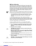
Most interface connectors are keyed for correct insertion; that is, a notch or a missing
pin on one connector matches a tab or a filled-in hole on the other connector (see Fig-
ure 7-5). Keying ensures that the pin-1 wire in the cable (indicated by the colored strip
along one edge of the cable) goes to the pin-1 end of the connector.
The pin-1 end of a connector on a board or a card is usually indicated by a silk-
screened “1” printed directly on the board or card.
&$87,21:KHQFRQQHFWLQJDQLQWHUIDFHFDEOHGRQRWUHYHUVHWKHLQWHUIDFH
FDEOHGRQRWSODFHWKHFRORUHGVWULSDZD\IURPSLQRIWKHFRQQHFWRU
5HYHUVLQJWKHFDEOHSUHYHQWVWKHGULYHIURPRSHUDWLQJDQGFRXOGGDPDJH
WKHFRQWUROOHUWKHGULYHRUERWK
,QVWDOOLQJD'ULYHLQD,QFK'ULYH%D\
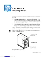
The 5.25-inch drive bays can accommodate any of the following types of half-height
drives:
A diskette drive or tape drive that uses the diskette/tape drive interface on the
system board
A CD-ROM or tape drive that uses the secondary EIDE interface on the system
board
A CD-ROM or tape drive that uses its own controller card
To install a drive in a 5.25-inch drive bay, follow these steps:
8QSDFNWKHGULYHDQGSUHSDUHLWIRULQVWDOODWLRQ
&$87,216*URXQG\RXUVHOIE\WRXFKLQJDQXQSDLQWHGPHWDOVXUIDFH
RQWKHEDFNRIWKHFRPSXWHU
:KHQ\RXXQSDFNWKHGULYHGRQRWVHWLWRQDKDUGVXUIDFHZKLFKPD\
GDPDJHWKHGULYH,QVWHDGVHWWKHGULYHRQDVXUIDFHVXFKDVDIRDP
SDGWKDWZLOOVXIILFLHQWO\FXVKLRQLW
Check the documentation that accompanied the drive to verify that the drive is
configured for your computer system. Change any settings necessary for your
configuration.
NOTE: If you are installing a non-EIDE tape drive, check the documentation for
the drive to determine the jumper or switch settings used to designate the drive
as drive address DS4 (not DS2 or DS3 as may be indicated in the drive documen-
tation). Unless the drive is already set to drive 4, reconfigure its jumper or switch
setting (see “Jumpers” and “Switches” in Chapter 5).
If you are installing an EIDE CD-ROM or EIDE tape drive, configure the drive for
the Cable Select setting.
Summary of Contents for OptiPlex G1
Page 1: ... ZZZ GHOO FRP HOO 2SWL3OH 0LQL 7RZHU 0DQDJHG 3 6 VWHPV 5 5 1 1 167 7 21 8 ...
Page 8: ...x ...
Page 20: ...xxii ...
Page 34: ...1 14 Dell OptiPlex G1 Mini Tower Managed PC Reference and Installation Guide ...
Page 56: ...2 22 Dell OptiPlex G1 Mini Tower Managed PC Reference and Installation Guide ...
Page 89: ...Working Inside Your Computer 5 9 LJXUH 6 VWHP RDUG XPSHUV jumpered unjumpered ...
Page 128: ...7 16 Dell OptiPlex G1 Mini Tower Managed PC Reference and Installation Guide ...
Page 134: ...A 6 Dell OptiPlex G1 Mini Tower Managed PC Reference and Installation Guide ...
Page 156: ...D 4 Dell OptiPlex G1 Mini Tower Managed PC Reference and Installation Guide ...


