background image

43

LCD Operation

|

System Info

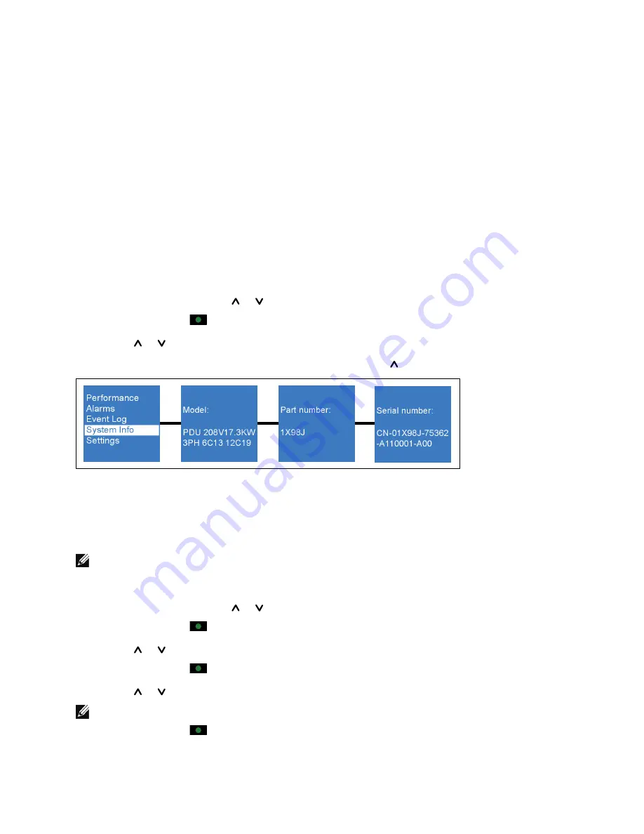
The System Info menu screens display the following rPDU identification information:

S

Type and model

S

rPDU part number

S

Serial number

S

NMC firmware version

S

NMC IP address

S

NMC MAC address

S

rPDU firmware

Retrieving System Identification Information

To retrieve rPDU system identification information:

1

From the Main menu, use the   or   buttons to navigate to the System Info menu.

2

Press and release the 

 button to select the System Info menu.

3

Use the   or   buttons to toggle the available options within the menu.

4

To exit any screen and return to the previous menu level, press the   button for longer than one second.

Figure 27. Example Identification Displays

Settings

The Settings menu provides user configuration options (see Figure 28). Only the available options display.

NOTE:


User settings are not protected by default. You can enable the password through the Password setting.

Retrieving or Changing Configuration Settings in the Settings Menu

1

From the Main menu, use the   or   buttons to navigate to the Settings menu.

2

Press and release the 

 button to select the Settings menu.

3

Use the   or   buttons to navigate to a submenu.

4

Press and release the 

 button to select the submenu.

5

Use the   or   buttons to toggle the available configuration options within a submenu.

NOTE:


When scrolling through the selections, the present setting displays for each selection.

6

Press and release the 

 button to select the configuration option you want to change.

Summary of Contents for Metered Rack Power Distribution Unit

Page 1: ...Dellt Metered Rack Power Distribution Unit rPDU User s Guide DELLM0001 DELLM001A DELLM0002 DELLM0003 DELLM0004 DELLM004A DELLM0005 DELLM0006 DELLM0007 w w w d e l l c o m s u p p o r t d e l l c o m ...

Page 2: ...epairs and service should be performed by AUTHORIZED SERVICE PERSONNEL ONLY There are NO USER SERVICEABLE PARTS inside the rPDU Information in this document is subject to change without notice E 2010 Dell Inc All rights reserved Reproduction in any manner whatsoever without the written permission of Dell Inc is strictly forbidden Trademarks used in this text Dell and the DELL logo are trademarks o...

Page 3: ...g Information 13 2 Safety Warnings 3 Installation Unpacking the rPDU 15 Inspecting the Equipment 16 Checking the Accessory Bag 16 Preparing for Installation 17 Installing Hardware for Options 17 Installing Strain Relief Brackets 17 Installing Deep Mounting Pegs 18 Installing the rPDU in the Rack Enclosure 19 Attaching the Ground Wire 21 Connecting the Protected Equipment 22 Starting the rPDU 22 Sh...

Page 4: ...ters 38 Alarms Menu 39 Retrieving Active Alarms 39 Event Log 42 Retrieving the Event Log 42 System Info 43 Retrieving System Identification Information 43 Settings 43 Retrieving or Changing Configuration Settings in the Settings Menu 43 6 Serial Interface Operation Supported Commands 50 Nomenclature 51 Connecting to the Internal rPDU NMC 51 Configuring the Network with a DHCP Server 54 Configuring...

Page 5: ... Uploading a Configuration File 74 Downloading a Configuration File 74 Configuring Default CSV File Opening Settings 75 Configuring Network Access and Control 75 Setting General TCP IPv4 Configuration Options 75 Setting General TCP IPv6 Configuration Options 76 Enabling TCP IP Network Controls 77 Adding and Rejecting IP Addresses for SNMP HTTP Access Control 78 Rejecting IP Addresses for SNMP HTTP...

Page 6: ...6 Table of Contents Clearing Logs 89 Saving Logs to an External File 89 Restarting the Internal rPDU NMC 90 ...

Page 7: ... protect server network and data storage equipment The rPDUs distribute power in the rack The rPDUs are mounted vertically in a recessed channel providing more room for cabling within the rack enclosure The recessed location distances the rPDU from the other equipment and does not interfere with the airflow in the rack enclosure Figure 1 Rack Enclosure with rPDU Installed 1 ...

Page 8: ...topology S The rPDU provides an environmental monitoring sensor port a dry contact sensor port a 10 100 Base T Ethernet port and a serial communication port S The LCD panel provides pushbutton controls for accessing performance monitoring data event notifications and user configured provisioning options S The rPDU provides an internal Dellt Network Management Card NMC for network communications Th...

Page 9: ...Figure 2 One or Two rPDUs Installed in the rPDU Tray The standard mounting orientation for the rPDU is 180 This is a snap in tooless installation Two factory installed mounting pegs are inserted in mounting keyholes on the wall of the rPDU tray NOTE The 180 orientation means that the mounting surface the back of the rPDU is 180 in relation to the front receptacles The rPDU can also be mounted in a...

Page 10: ...ated on the rPDU front panel may be used to bond other conductive metal components in the rack enclosure to a ground reference point for signaling or other functional purposes This bonding point can also be used to bond the rPDU to a known earthed reference terminal in the building Per international regulatory requirements the primary Safety Earth Bond connection is contained in the rPDU as an int...

Page 11: ...4 Pin Plug 4 or Wye 5 Pin Plug 5 Maximum Amperage A Rating Plug P Receptacle Socket R or Connector C Clock Position PE 6 or 9 Waterproof W or Splash Resistant S DELLM0001 460P9W 4 60 P 9 W DELLM001A 460P9W 4 60 P 9 W DELLM0002 532P6S 5 32 P 6 S DELLM0003 516P6S 5 16 P 6 S DELLM0004 460P9W 4 60 P 9 W DELLM004A 460P9W 4 60 P 9 W DELLM0005 532P6S 5 32 P 6 S DELLM0006 460P9W 4 60 P 9 W DELLM0007 532P6...

Page 12: ...unication and Monitoring Ports Two communication ports are provided The rPDU has a serial port for an RJ 45 to DB 9 cable provided for serial communication The rPDU also has a 10 100 Base T Ethernet port for network communication The network communication channel can be used to perform firmware upgrades flash upgrades over the network Upgrades can be performed for rPDUs installed in the rack enclo...

Page 13: ... can be found at support dell com S How to install the rPDU S rPDU specifications S How to configure rPDU settings S How to operate the rPDU Dell Metered rPDU User s Guide The user s guide is available at support dell com support edocs ACC PDU S Safety instructions S Regulatory information S Recycling information Safety Environmental and Regulatory Information S Warranty information S Terms and Co...

Page 14: ...educe the risk of fire or electric shock install this rPDU in a temperature and humidity controlled indoor environment free of conductive contaminants Ambient temperature must not exceed 50 C 122 F Do not operate near water or excessive humidity 95 maximum S To comply with international standards and wiring regulations the total equipment connected to the output of this rPDU must not have an earth...

Page 15: ... and on the rPDU Do not install the rPDU until the inside and outside are dry Use care when moving and opening the carton Leave the components packaged until ready to install 1 Remove the top from the carton see Figure 5 Figure 5 Unpacking the rPDU 2 Remove the rPDU the accessory bag and documentation from the carton Grasp the rPDU and the input connector plug and set them on a flat stable surface...

Page 16: ...he damage claim within 15 days to your service representative Checking the Accessory Bag The rPDU accessory bag includes the following S 2 deep mounting pegs and 2 8 32 5 8 mounting screws for 90 installation S Grounding kit with 1 silver 10 32 0 5 pan head screw 1 black M5 12 pan head screw 1 ground wire 2 star washers S Safety Environmental and Regulatory Information SERI document S Quick Start ...

Page 17: ... include the orientation of the rPDU and the type of strain relief brackets mounted on the rPDUs Installing Hardware for Options Install the hardware that supports installation options before installing the rPDUs in the rack enclosure This includes the following S Strain relief brackets for cord management optional kit S Deep mounting pegs for the 90 mounting option supplied NOTE The factory insta...

Page 18: ...ag 2 Locate the top and bottom peg mounting holes on the side of the rPDU see Figure 7 3 Align the peg mounting holes on the rPDU with the mounting hole in the center of the deep mounting pegs 4 Secure the top and bottom deep mounting peg with the provided screws see Figure 7 NOTE Dell recommends removing the standard mounting pegs on the rear of the rPDU if you install the deep mounting pegs prov...

Page 19: ...r keyholes in the rPDU tray for mounting the rPDU 3 Align the mounting pegs with the keyholes in wall of the rPDU tray see Figure 8 Figure 8 Aligning and Inserting the Standard or Deep Mounting Pegs Top Mounting shown Bottom Mounting not shown 4 Fully insert both mounting pegs into the keyholes 5 Push down to set the rPDU in place NOTE A second rPDU can be installed in the same tray The procedure ...

Page 20: ...20 Installation Figure 9 Mounting Two rPDUs in the PDU Tray 6 Continue to Attaching the Ground Wire section on page 21 ...

Page 21: ...e front panel of the rPDU using the silver 10 32 0 5 pan head screw and star washer supplied 2 Connect the other end of the ground wire to a hole in the rack frame using the black M5 12 pan head screw and star washer supplied See Figure 10 Ground Bonding Point Connection 10 32 0 5 Pan head Screw Silver Star Washer Frame Connection M5 12 Pan head Screw Black Star Washer Figure 10 Ground Bonding Poi...

Page 22: ... rPDU power cord into a power outlet 4 Ensure that each circuit breaker is in the ON position NOTE If power to the rPDU is interrupted check each circuit breaker and reset if necessary Starting the rPDU To start the rPDU 1 Plug the rPDU power cord into the power outlet 2 Turn each circuit breaker to the ON position 3 If power to the rPDU is interrupted check each circuit breaker and reset if neces...

Page 23: ...LM0002 Figure 12 24 DELLM0003 Figure 13 24 DELLM0004 Figure 14 25 DELLM004A Figure 14 25 DELLM0005 Figure 15 25 DELLM0006 Figure 16 26 DELLM0007 Figure 17 26 Output Receptacles 6 IEC 320 C13 10A 12 IEC320 C19 16A 6 20A Circuit Breakers IEC60309 60A Waterproof IP 67 460P9W 42U Side Mounted or Front Mounted Strain Relief Bracket Optional Figure 11 DELLM0001 and DELLM001A ...

Page 24: ...s Output Receptacles 18 IEC 320 C13 10A 12 IEC320 C19 16A IEC60309 32A Splash resistant IP 44 532P6S Figure 12 DELLM0002 42U Output Receptacles 21 IEC 320 C13 10A 6 IEC320 C19 16A IEC60309 16A Splash resistant IP 44 516P6S Side Mounted or Front Mounted Strain Relief Bracket Optional Figure 13 DELLM0003 ...

Page 25: ...nal Output Receptacles 42 IEC 320 C13 10A IEC60309 60A Waterproof IP 67 460P9W Figure 14 DELLM0004 and DELLM004A Side Mounted Strain Relief Bracket Optional 42U 6 20A Circuit Breakers Output Receptacles 42 IEC 320 C13 10A IEC60309 32A Splash resistant IP 44 532P6S Figure 15 DELLM0005 ...

Page 26: ...t Breakers Output Receptacles 48 IEC 320 C13 10A IEC60309 60A Waterproof IP 67 460P9W Figure 16 DELLM0006 48U 6 20A Circuit Breakers Output Receptacles 48 IEC 320 C13 10A IEC60309 32A Splash resistant IP 44 532P6S Side Mounted Strain Relief Bracket Optional Figure 17 DELLM0007 ...

Page 27: ...erface CLI upgrade utility or a Web based graphical user interface NOTE The RESET button on the front panel resets the internal NMC Flash upgrades are transparent and do not affect rPDU operation However the front panel buttons and LCD operation are disabled during the upgrade Unique model identification information prevents an incorrect firmware load from being installed on an rPDU during a flash...

Page 28: ...onnector to the rPDU serial communication port see Figure 18 3 Connect the serial cable console connector to the RS 232 serial connection port COM port on the PC NOTE Use HyperTerminal or an equivalent terminal emulation application for the CLI The cable pins for the RS 232 serial connection DB 9 female connector are identified in Figure 19 3 8 7 9 1 6 2 4 5 Figure 19 DB 9 Female Connector Table 2...

Page 29: ...rk 1 Locate the Ethernet cable to use for this network connection not provided 2 Ensure the network cable is connected to the network server or router connection 3 Connect the Ethernet cable to the Ethernet connection port on the rPDU see Figure 18 Monitoring Ports Monitoring ports are used to collect readings from connected sensors There are two types of environmental monitoring device EMD ports ...

Page 30: ... dry contact becomes active when the pins are shorted When configured as normally closed the dry contact becomes active when the pins are open See the Settings menu on page 43 NOTE When the dry contact is active an alarm displays The alarm is cleared by restoring the hardware connection to the state before the dry contact became active Install and set up the dry contact sensor as instructed in the...

Page 31: ...ton graphical LCD panel see Figure 20 Use the control buttons to change the screen display and retrieve specific performance data or change configuration values The display view can also change automatically For example the display changes to show active alarms as they occur or particular displays update due to a change in operating state Inactivity can cause a screen change as well For example th...

Page 32: ...ons Table 5 LCD Control Button Functions Control Button Operator Action Response Press for less than one second Scroll up moving back to the previous menu Press for longer than one second Return exit back one menu layer without initiating a command or changing a setting Press for less than one second Select the menu or option to be changed Press for longer than one second Save the setting being ed...

Page 33: ...Alarm Notification When an alarm occurs the LCD display automatically changes to the active alarm display except under the following circumstances S Screen lock is activated S You are in the Settings menu S You selected a control button in the last five seconds NOTE An active alarm is presented as amber text on a dark background to distinguish it from the standard LCD display Input Status Screen F...

Page 34: ...attage of the rPDU reported in Watts W This is also called active power Input Volt amperes VA Calculated value of the overall input volt amperes VA of the rPDU This is also called apparent power Main Menu Selections The rPDU menu selection hierarchy provides useful performance information alarms events identification and configuration settings Make a selection from the rPDU Main Menu to retrieve p...

Page 35: ...on information such as model serial number and firmware version identification Settings The Settings menu provides configuration options for customizing performance monitoring thresholds and configuring the user interface NOTE For Delta models L1 represents L1 L3 data L2 represents L1 L2 data and L3 represents L2 L3 data Selecting a Menu To select a menu 1 From the Main menu use the or button to n...

Page 36: ...e the or buttons to navigate to a submenu 4 Press and release the button to select the submenu 5 Use the or buttons to toggle the available options within a submenu NOTE When scrolling through the selections the up to date data displays for each selection 6 To exit any screen and return to the previous menu level press the button for longer than one second Figure 24 Example Performance Displays Ta...

Page 37: ...ge Present voltage reading for phase 2 L2 displayed in Volts V L2 Frequency Present frequency reading for phase 2 L2 displayed in Hertz Hz L2 Current Present current reading for phase 2 L2 displayed in Amps A L3 Menu L3 Voltage Present voltage reading for phase 3 L3 displayed in Volts V L3 Frequency Present frequency reading for phase 3 L3 displayed in Hertz Hz L3 Current Present current reading f...

Page 38: ...ensors connected Displays the temperature in C on the Temperature screen Displays the humidity percentage on the Humidity screen Measured and Calculated Meters The rPDU operating status information provided by the Performance menu selections is derived from a series of measured and calculated meters See Table 9 for descriptions of measured and calculated meters Table 9 Measured and Calculated Mete...

Page 39: ...DD YYYY Current time and date reading from the network interface card real time clock Alarms Menu Selecting the Alarms menu allows you to review all active alarms in the order of occurrence If there are no active notices or alarms a No Active Alarm message appears see Figure 25 In addition to displaying in the Alarms menu alarms and notices are logged in the Event Log NOTE Events are not shown in ...

Page 40: ...es an alarm and is logged in the Event Log Alarm L2 Over Current Alarm The Phase 2 input current amperage A reading is greater than the value configured as the over current alarm threshold Generates an alarm and is logged in the Event Log Alarm L3 Over Current Alarm The Phase 3 input current amperage A reading is greater than the value configured as the over current alarm threshold Generates an al...

Page 41: ... C below the Temperature High Alarm Level value setting Generates an alarm and is logged in the Event Log Alarm Over Temperature Warning The temperature level reading is greater than the warning temperature threshold value This alarm clears when the temperature drops 5 C below the Temperature High Warning Level value setting Generates an alarm and is logged in the Event Log Notice Low Humidity War...

Page 42: ... mm ss at which the event occurred The second row contains the type of event and code The event description begins on the third row and may continue to the fourth row The bottom right corner of the event screen displays two numbers an ordering number of the event in the log followed by the total number of events in the log If there are no events in the log the screen displays No events in log Retr...

Page 43: ...han one second Figure 27 Example Identification Displays Settings The Settings menu provides user configuration options see Figure 28 Only the available options display NOTE User settings are not protected by default You can enable the password through the Password setting Retrieving or Changing Configuration Settings in the Settings Menu 1 From the Main menu use the or buttons to navigate to the ...

Page 44: ...set 8 Set a new value by pressing the button again for longer than one second 9 To exit any screen and return to the previous menu level press the button for longer than one second Figure 28 Example Settings Displays Table 11 provides descriptions of Settings menu selections ...

Page 45: ...1 Over Current Warning Level 0 0A 48 0A 0 0A 32 0A 0 0A 16 0A An input current amperage A reading greater than this value causes a warning to generate This warning indicates that the current A reading has risen to an unacceptable level 38 4A 25 6A 12 8A L1 Over Current Alarm Level 0 0A 48 0A 0 0A 32 0A 0 0A 16 0A An input current amperage A reading greater than this value causes an over current al...

Page 46: ...A reading is reduced to an unacceptable level 0 0A 0 0A 0 0A L3 Settings L3 Over Current Warning Level 0 0A 48 0A 0 0A 32 0A 0 0A 16 0A An input current amperage A reading greater than this value causes a warning to generate This warning indicates that the current A reading has risen to an unacceptable level 38 4A 25 6A 12 8A L3 Over Current Alarm Level 0 0A 48 0A 0 0A 32 0A 0 0A 16 0A An input cu...

Page 47: ...egree C 65 degree C A high temperature warning threshold is exceeded when a value greater than this setting is detected by the environmental temperature sensor A high temperature warning generates 59 degree C Temperature High Alarm Level 0 degree C 65 degree C A high temperature alarm threshold is exceeded when a value greater than this setting is detected by the environmental temperature sensor A...

Page 48: ...ssword is USER and all settings are password protected NOTE If you enter an incorrect password the message Incorrect Password appears Press any button to return to the password screen and retry the password Disabled Factory setting Restore Factory Defaults No Yes If No no action If Yes all configurable settings are restored to factory default values NOTE When you select Yes and press the select bu...

Page 49: ...on the LCD display screen adjusts immediately as the Up and Down buttons are pressed Once you reach the optimal contrast press and hold the Select button for one second to set the new contrast 0 LCD Orientation 0 degree 180 degree The LCD orientation is adjustable to accommodate both horizontal 0 degree setting and vertical 180 degree setting views 0 degree DELLM0001 DELLM001A DELLM0004 DELLM004A ...

Page 50: ...S Set or retrieve rPDU critical alarm high threshold values S Set or retrieve high temperature warning or alarm threshold values and low humidity warning or alarm threshold values S Set or retrieve settings for dry contact sensors connected to the rPDU S Retrieve selected rPDU equipment software version and ratings information S Reset the rPDU settings to factory defaults or reboot the rPDU NOTE T...

Page 51: ... 2 Z L3 Phase 3 1 Line to Neutral voltage will not be reported on a Delta configured rPDU 2 Line to Line voltage will not be reported on a Wye configured rPDU Connecting to the Internal rPDU NMC NOTE The following instructions describe the procedure to establish and save a serial interface connection to an rPDU using HyperTerminal The serial interface is supported on Microsoft Windows 2000 XP 2003...

Page 52: ...ot display when the New connection Hyper Terminal window opens select File New Connection from the File menu to open the dialog Figure 29 Create a Serial Connection 6 Enter a name for the connection in the Name field Select an icon representing the type of connection you will use then click OK see Figure 29 7 On the Connect To dialog provide the communication details for connecting to the rPDU you...

Page 53: ...ttings Port Setting Value Baud Rate 9600 Data Bits 8 Parity None Stop Bits 1 Flow Control None 9 The HyperTerminal session window opens for the connection you selected The cursor is poised at the command line to begin your session 10 Continue to one of the following sections to configure the network settings Configuring the Network with a DHCP Server on page 54 Configuring the Network without a DH...

Page 54: ...twork Settings 1 Read NetworkSettings 2 Modify Network Settings 3 Set Ethernet Speed 0 Exit Select an option 1 5 At the Select an option prompt type 1 and press Enter The network configuration settings display see the following example Network configuration MAC address 00 22 19 FF 8E 13 Mode DHCP IP address 166 99 224 48 Subnet mask 255 255 255 0 Gateway 166 99 224 1 Link Local IPv6 address FE80 2...

Page 55: ...ain IP settings from the network N N Static IP address 166 99 1 2 166 99 21 21 Static IP address is 166 99 21 21 Subnet Mask IP address 255 255 248 0 255 255 255 0 Subnet Mask IP address is 255 255 255 0 Gateway address IP address 166 99 17 1 166 99 17 1 Gateway address IP address is 166 99 17 1 Wait while your new configuration is saved Reset the card to enable the new configuration 4 Follow the ...

Page 56: ...e the current critical alarm threshold settings for one or all rPDU phase lines rPDU alarm Example rPDU alarm Alarm threshold on rPDU is 2000W Alarm threshold on rPDU phase X is 24 0A Alarm threshold on rPDU phase Y is 24 0A Alarm threshold on rPDU phase Z is 24 0A Set the threshold for the alarm level of a total of all phases on the rPDU rPDU alarm threshold NOTE The threshold value you set shoul...

Page 57: ...se Y 0 2A rPDU RMS current for phase Z 0 1A Retrieve a summary of current measurements for each rPDU phase L1 L2 or L3 rPDU current summary Example rPDU current summary X 0 1A 0 0A 0 0A 0 0A Y 0 2A 0 0A 0 0A 0 0A Z 0 3A 0 0A 0 0A 0 0A NOTE The summary response shows the present current reading as the first value the other three values minimum maximum and average will always be reported as zero Ret...

Page 58: ... interface for the rPDU Usage rPDU exit Log out of the serial CLI rPDU exit Example rPDU exit Dell rPDU model Copyright c 2010 Dell Corporation DELL DPI 00 01 0028 August 5 2010 Username where rPDU model Dell model part number See Table 14 for valid values Table 14 rPDU model Value Descriptions rPDU model Value rPDU model Descriptions 1X98J PDU 208V 17 3KW 3PH 6C13 12C19 DELLM0001 7P35N PDU 200V 1...

Page 59: ...specified commands Usage rPDU help rPDU command help where command alarm current exit factory_defaults network power reboot sensors temperature voltage ver List all available rPDU CLI commands rPDU help Example rPDU help Available commands alarm current exit factory_defaults help network power reboot sensors temperature voltage ver List detailed help on a specific rPDU CLI command rPDU command hel...

Page 60: ...00A 222 19FF FFF 8E13 64 Access the serial interface CLI to modify network configuration Network Settings 1 Read NetworkSettings 2 Modify Network Settings 3 Set Ethernet Speed 0 Exit Select an option 2 For each of the following questions you can press Return to select the value shown in braces or you can enter a new value Should this target obtain IP settings from the network N N Static IP address...

Page 61: ...etrieve a summary of current consumption and peak consumption watts power readings rPDU power summary Example rPDU power summary rPDU 1 0W 2 0W 0 0W 0 0W NOTE The summary command response shows the present power as the first parameter and the peak consumption watts as the second parameter The minimum and average values will always be reported as zero Reset the peak consumption watts power readings...

Page 62: ...PDU sensors threshold Example rPDU sensors threshold rPDU temperature thresholds on sensor T1 60 0C 59 0C rPDU humidity thresholds on sensor H1 10 0 0 0 NOTE The retrieved threshold value displays in a format of high value then low value separated by colons Retrieve present thresholds for a specific environment monitoring sensor connected to an rPDU rPDU sensors threshold name Example rPDU sensors...

Page 63: ...odel 09FG8 3 phases wye where outlets Total number of outlets regardless of outlet type see Table 15 maxcurrent Maximum current for the rPDU wattrating Maximum wattage rating for the rPDU sw Software version number model Dell Part Number see Table 15 3 phases delta wye For an rPDU with 3 phase output only Delta or Wye configuration Table 15 model and outlets Value Description model Values model De...

Page 64: ... and Z L1 Phase to Phase on a Delta configured rPDU XY RMS voltage between X and Y L2 Phase to Phase on a Delta configured rPDU YZ RMS voltage between Y and Z L3 Phase to Phase on a Delta configured rPDU 1 Line to Neutral voltage will not be reported on a Delta configured rPDU 2 Line to Line voltage will not be reported on a Wye configured rPDU Usage rPDU voltage summary XN YN ZN XZ XY YZ where su...

Page 65: ...hase NOTE The summary option response displays the present power as the first parameter and the peak consumption watts as the second parameter The minimum and average values will always be reported as zero Three Phase Wye Example rPDU voltage summary XN 229V 0V 0V 0V YN 230V 0V 0V 0V ZN 231V0V 0V 0V Three Phase Delta Example rPDU voltage summary XY 208V 0V 0V 0V YZ 209V 0V 0V 0V XZ 207V 0V 0V 0V R...

Page 66: ...ot configurable Only English is provided NOTE The data that displays on the Web interface depends on the rPDU model you are using The examples shown represent typical data displays reported from a single model NOTE The two most recent Microsoft Internet Explorer and Firefox browser versions are currently supported Navigating the Web Interface The Dell DPI is a graphical Web interface used to remot...

Page 67: ...ed the corresponding information displays on the Main Page The top of the page displays the title and a Help link Click Help on any page to see online help for the currently displayed page NOTE You can expand your view of the Main Page contents vertically using the elevator tab on the side of the page If you need more window viewing area you can resize the window to a wider or taller size Operatio...

Page 68: ...is default address change the IP address using the serial interface before using any of the network interfaces See Serial Interface Operation on page 50 for more information To access the Web interface 1 Open the Web browser and navigate to the IP address of the rPDU 2 Click the Dell logo start button to log in see Figure 33 Figure 33 Start Button 3 Enter a valid user name and password in the Auth...

Page 69: ...r Name and Password table 3 To change the administrator user name enter the new password in the Administrator User Name field 4 To change the administrator password enter the new password in the Administrator Password field The characters appear as asterisks 5 Enter the new password in the Confirm Administrator Password field The characters appear as asterisks 6 Click Save to apply the new user na...

Page 70: ...r go to Step 5 To set the time and date manually go to Step 9 3 Select the Synchronize with computer time radio button The current computer date and time displays 4 Go to Step 10 5 Select the Synchronize with NTP server radio button 6 Type the NTP server address or DNS host address in the appropriate field then select the time zone from the list 7 Optional Enable Daylight Savings Time by selecting...

Page 71: ...ress the From field of the Email will be account ipv4_address or account ipv6_address SMTP Reply to Address The address to which the user will reply when the event mail is received SMTP Port Number The SMTP port number You can enter a port number other than the standard port setting for SMTP port 25 Identifying Email Notification Recipients NOTE Only the administrator can configure these settings ...

Page 72: ... notification for Events or Events Status mail types This filter is based on the SNMP based traps Selections include Critical Major Minor or All Mail Daily Report Level Sets the hour of the day the Email notification will be sent Daily Status mail type only Valid values are 00 00 23 00 Creating Links to External Web Sites NOTE After external links are created the link can be enabled to display at ...

Page 73: ...ngs can be viewed in this table at any time Table 20 describes the attributes in the System table Table 20 System Attribute Description System Name Dell system name Limited to 31 characters The default value is Dell PDU System Contact System manager defined in MIB II Limited to 31 characters System Location System installation locality defined in MIB II Limited to 31 characters Data Log Interval S...

Page 74: ...a configuration file 1 From the System menu click Configuration The Configuration page displays 2 Under Upload Download click the Download Configuration icon 3 Does the file download dialog box display or does the file data display in the browser window If the dialog box displays go to Step 4 If the file data displays in the Browser window go to Configuring Default CSV File Opening Settings on pag...

Page 75: ...t the steps to correct the default file opening settings for the file type XLS NOTE After these settings are corrected other configuration files will download properly 2 This procedure is completed Configuring Network Access and Control This section explains S Setting general IPv4 and IPv6 configuration options S Enabling TCP IP network controls S Setting SNMP HTTP access control S Configuring SNM...

Page 76: ...Dell DPI in dotted format Limited to 15 characters Subnet mask 255 255 0 0 is the default value DNS Address IP address of your network DNS server This is a required entry if you entered a Host name for the Mail Server in the Email Configuration table on the Email Notification page Otherwise 0 0 0 0 will be the value in the DNS Address field Setting General TCP IPv6 Configuration Options To configu...

Page 77: ...munication If IPv6 auto configuration is enabled and successfully auto configures the IPv6 global address the status reported in this field is Valid If the IPv6 auto configuration fails or if auto configuration is disabled and manual configuration fails the status reported in this field is Invalid NOTE The IPv6 link local address is always valid on the same link or subnet Link Local Address READ O...

Page 78: ...HTTP Support Enable or disable the HTTP connection with the Dell DPI You can configure the HTTP protocol to use a port number other than standard HTTP port 80 Adding and Rejecting IP Addresses for SNMP HTTP Access Control NOTE The default IP address setting is 255 255 255 255 To set and accept IP addresses 1 From the Network menu click Access Control The SNMP HTTP Access Control page displays 2 En...

Page 79: ...ork menu click SNMP Configuration The SNMP Configuration page displays 2 Enter configuration values in the SNMP Protocol Settings table see Table 25 3 Click Save 4 This procedure is completed Table 25 describes the attributes in the SNMP Protocol Settings table Table 25 SNMP Protocol Settings Attribute Description SNMP Status Enable or disable the SNMP connection with the Dell DPI SNMP UDP Port Si...

Page 80: ...on address to which the trap should be sent The NMS address is entered in dotted format IP address can be IPv4 IPv6 or DNS host name Community Community string of the trap rPDU to be sent Limited to 15 characters Trap Type Disables traps or receives traps based on Dell DPI MIB Selections are Disabled or MIB Trap Severity Severity level of the trap to be received Selections are S All Traps All trap...

Page 81: ...rnings S Managing environmental sensors S Monitoring alarms and events S Managing event and data logs S Restarting the internal rPDU NMC Viewing Present rPDU Status NOTE The Summary table always displays on the Main Page when the Web interface opens To view the present rPDU status 1 From the Power Management menu click Summary The Summary page displays 2 Review the present values for the rPDU see ...

Page 82: ... value of the overall input volt amperes VA of the rPDU This is also called apparent power PDU Total Rating Current A Present current measured at 3 f input of the rPDU reported in amperes A Viewing rPDU and Web SNMP Card Identification To view rPDU and Web SNMP card identification 1 From the System menu click Identification The Identification page displays 2 Review the PDU Identification table and...

Page 83: ...3 This procedure is completed Table 28 describes the attributes in the Input Statistics tables Table 28 Input Statistics Table Attribute Description Present Values Phase 1 Phase 2 and Phase 3 PDU Input Voltage V Present voltage reading for Phase 1 Phase 2 and Phase 3 displayed in Volts V PDU Input Current A Present current reading for Phase 1 Phase 2 and Phase 3 displayed in Amps A A meter bar pro...

Page 84: ... NOTE This value accumulates If this value reaches the maximum value for a 32 bit number do not reset Click Reset to clear this value to zero 0 and reset the time to the present time Input Thresholds Phase 1 Current Thresholds A Low Warning Causes an alarm when the input current amperage A reading falls below the low warning threshold value displayed in the table High Warning Causes an alarm when ...

Page 85: ...xceeds the high critical threshold value displayed in the table Input Thresholds Load Thresholds W For Phase 1 Phase 2 or Phase 3 Causes an alarm when the total watts W reading for all three phases exceeds the overload warning threshold value displayed in the table NOTE If you correct any threshold values in this table click Save to save your changes Figure 40 Input ...

Page 86: ...E If a sensor is not connected to the rPDU a Non active value displays NOTE If you change any sensor threshold values you must click Save to save your changes see Table 29 3 This procedure is completed Table 29 describes the attributes in the Environment tables Table 29 Environment Table Attribute Description Present Values Temperature C Displays the temperature in C on the Temperature screen A me...

Page 87: ...lues The Hysteresis Value displays read only Humidity Thresholds Low Warning Low Critical Alarm Humidity percentage threshold setting in the range of 0 0 95 0 The Hysteresis Value displays read only Dry Contact The operation setting for Dry Contact 1 or Dry Contact 2 Selections are Normally Closed or Normally Open NOTE If you correct any threshold values in this table click Save to save your chang...

Page 88: ...arm Event Table page displays 2 Review the present alarms and events for the rPDU 3 This procedure is completed Viewing Event and Data logs NOTE The logs list all entries that have occurred since the table was cleared The accumulated entries are overwritten when a maximum of 50 entries are collected The logs can also be cleared manually with the Logs menu bar Clear and Save selection To view event...

Page 89: ...re is completed Saving Logs to an External File NOTE The logs are saved to your computer as a spreadsheet in CSV format To save logs to an external file 1 From the Logs menu bar click Clear Save The Clear and Save page displays 2 Under Save Log Data click the icon for the type of log you want to save S Data Log S NMC Event Log S PDU Event Log 3 Does the file download dialog box display or does the...

Page 90: ...on Restarting the Internal rPDU NMC To restart the rPDU NMC 1 From the System menu click Configuration The Configuration page displays 2 Under Control click the Restart NMC button The NMC restarts 3 This procedure is completed ...

Reviews: