


Diagnostic aids
3-1
3. Diagnostic aids
Accessing service menus
There are two different test menus that can be accessed during POR to identify problems with the printer.
Printing menus
To print a listing of the states and settings of the printer:
1.
At the
Ready
prompt, press
under
Menu
until
Utilities
appears.
2.
Press .
3.
Press
until
Print Menus
appears.
4.
Press .
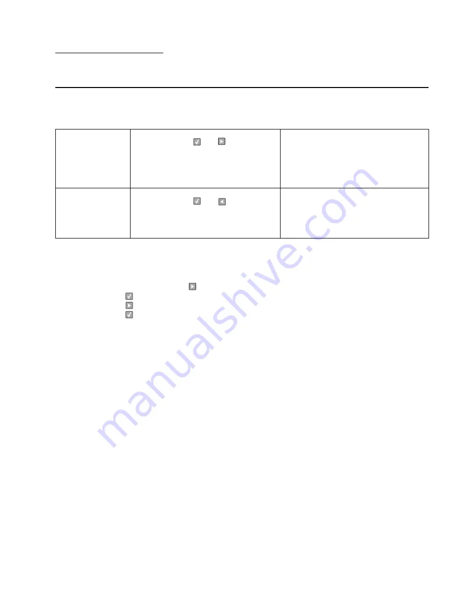
Configuration Menu
1. Turn off the printer.
2. Press and hold
and
.
3. Turn on the printer.
4. Release the buttons when
Performing Self
Test
displays.
5. The message
CONFIG MENU
displays on the
top line of the operator panel.
The Configuration menu group contains a set
of menus, settings, and operations which are
infrequently required by a user. Generally, the
options made available in this menu group are
used to configure a printer for operation.
See
“Available menus” on page 3-2
.
Diagnostics Mode
1. Turn off the printer.
2. Press and hold
and
.
3. Turn on the printer.
4. Release the buttons when
Performing Self
Test
displays.
The Diagnostic menu group contains the
settings and operations used while
manufacturing and servicing the printer.
See
“Menus may vary depending on the
features and options of the printer.” on
page 3-5
.
Summary of Contents for Inspiron One 2330
Page 1: ...Dell 2330d dn Service Manual 11 Dec 2008 ...
Page 6: ...vi ...
Page 11: ...Notices and safety information xi ...
Page 12: ...xii ...
Page 26: ...1 10 ...
Page 96: ...6 Remove the screw D from the gear E 7 Remove the plastic bushing F 4 14 ...
Page 103: ...Repair information 4 21 5 Disconnect the AC cable C 6 Disconnect the thermistor cable D C B D ...
Page 117: ...Repair information 4 35 5 Remove the three screws B from the left door mount B ...
Page 120: ...8 Use a screwdriver to pop the inner shaft lock B loose 9 Remove the inner shaft lock C 4 38 ...
Page 123: ...Repair information 4 41 5 Remove the e clip B 6 Remove the media feed clutch with cable C ...
Page 129: ...Repair information 4 47 7 Open the front access door and remove the lower paper guide ...
Page 137: ...Repair information 4 55 4 Tilt the rear cover and remove ...
Page 150: ...Controller board connector pin values 5 2 ...
Page 154: ...6 2 ...
Page 156: ...Assembly 1 Covers 4 3 1 5 2 9 10 6 7 8 11 12 13 7 2 ...
Page 158: ...Assembly 2 Electronics 5 2 6 3 4 10 11 12 7 13 8 9 1 7 4 ...
Page 160: ...Assembly 3 Frame 7 1 2 5 6 7 12 8 See instruction sheet in the FRU 9 10 11 3 4 3 7 6 ...
Page 164: ...7 10 ...


