


Diagnostics information
2-37
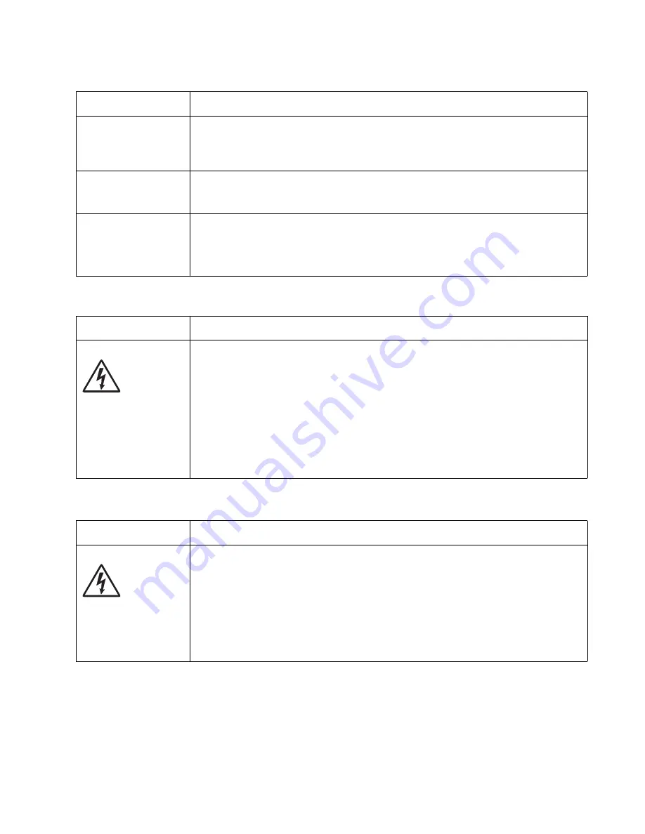
Printhead service check
Transfer roll service check
Unexpected
characters print, or
characters are
missing.
• Ensure correct printer driver is being used.
• Select hex trace mode to determine what the problem is.
• Restore factory defaults.
• Make sure the parallel cable or USB cable is firmly plugged in at the back of the printer.
Jobs are not printing,
and an error message
is displayed.
• The printer is waiting for an appropriate command.
• Make sure the print cartridge assembly is installed properly.
• Make sure the printer front cover is closed.
While in PostScript 3
emulation, the printer
is flushing data (an
error message is
displayed).
• Ensure the correct PostScript driver is being used.
• The printer doesn’t have enough memory to print the job. Install more memory.
FRU
Action
Printhead
Note:
New printhead
must be aligned. See
“Printhead assembly
electronic
adjustment” on
page 3-16
.
Turn the printer off.
Disconnect the printhead cables from J8 and J100 on the controller board.
Turn the printer on with the front door closed.
On the controller board, 5 V dc on pin 10 at J8 and +5 V dc on pins 1, 2, and 3 at
J100.
Verify grounds on pins 2, 4, and 7 at J8 and on pin 4 at J100.
• If voltages or grounds are incorrect, then check the controller board. See
“Controller
board service check” on page 2-22
for more information.
• If voltages are correct, then replace the printhead (comes with cables).
FRU
Action
Transfer roll
Note:
Do not touch the transfer roll except at its ends. Place a sheet of paper over the roll to
prevent damage from finger oils or hand lotion.
Check the springs in the left and right transfer roll bearings. Do not try to move the left
spring. The bearing assemblies should support the transfer roll, applying evenly distributed
forces to the PC drum.
Replace the transfer roll assembly if the springs or bearings show signs of damage, or
fatigue.
Inspect the transfer roll for signs of wear, damage or contamination.
Replace as necessary.
Print quality problems (Continued)
Problem
Cause / action
Summary of Contents for Inspiron One 2330
Page 1: ...Dell 2330d dn Service Manual 11 Dec 2008 ...
Page 6: ...vi ...
Page 11: ...Notices and safety information xi ...
Page 12: ...xii ...
Page 26: ...1 10 ...
Page 96: ...6 Remove the screw D from the gear E 7 Remove the plastic bushing F 4 14 ...
Page 103: ...Repair information 4 21 5 Disconnect the AC cable C 6 Disconnect the thermistor cable D C B D ...
Page 117: ...Repair information 4 35 5 Remove the three screws B from the left door mount B ...
Page 120: ...8 Use a screwdriver to pop the inner shaft lock B loose 9 Remove the inner shaft lock C 4 38 ...
Page 123: ...Repair information 4 41 5 Remove the e clip B 6 Remove the media feed clutch with cable C ...
Page 129: ...Repair information 4 47 7 Open the front access door and remove the lower paper guide ...
Page 137: ...Repair information 4 55 4 Tilt the rear cover and remove ...
Page 150: ...Controller board connector pin values 5 2 ...
Page 154: ...6 2 ...
Page 156: ...Assembly 1 Covers 4 3 1 5 2 9 10 6 7 8 11 12 13 7 2 ...
Page 158: ...Assembly 2 Electronics 5 2 6 3 4 10 11 12 7 13 8 9 1 7 4 ...
Page 160: ...Assembly 3 Frame 7 1 2 5 6 7 12 8 See instruction sheet in the FRU 9 10 11 3 4 3 7 6 ...
Page 164: ...7 10 ...


