


Most paper jams can be avoided by correctly loading paper and specialty media in the printer.
The following hints can help prevent paper jams:
•
Use only the recommended print media.
•
Do not overload the print media sources. Make sure the stack height does not exceed the maximum height
indicated by the stack line on the labels in the sources.
•
Do not load wrinkled, creased, damp, or curled print media.
•
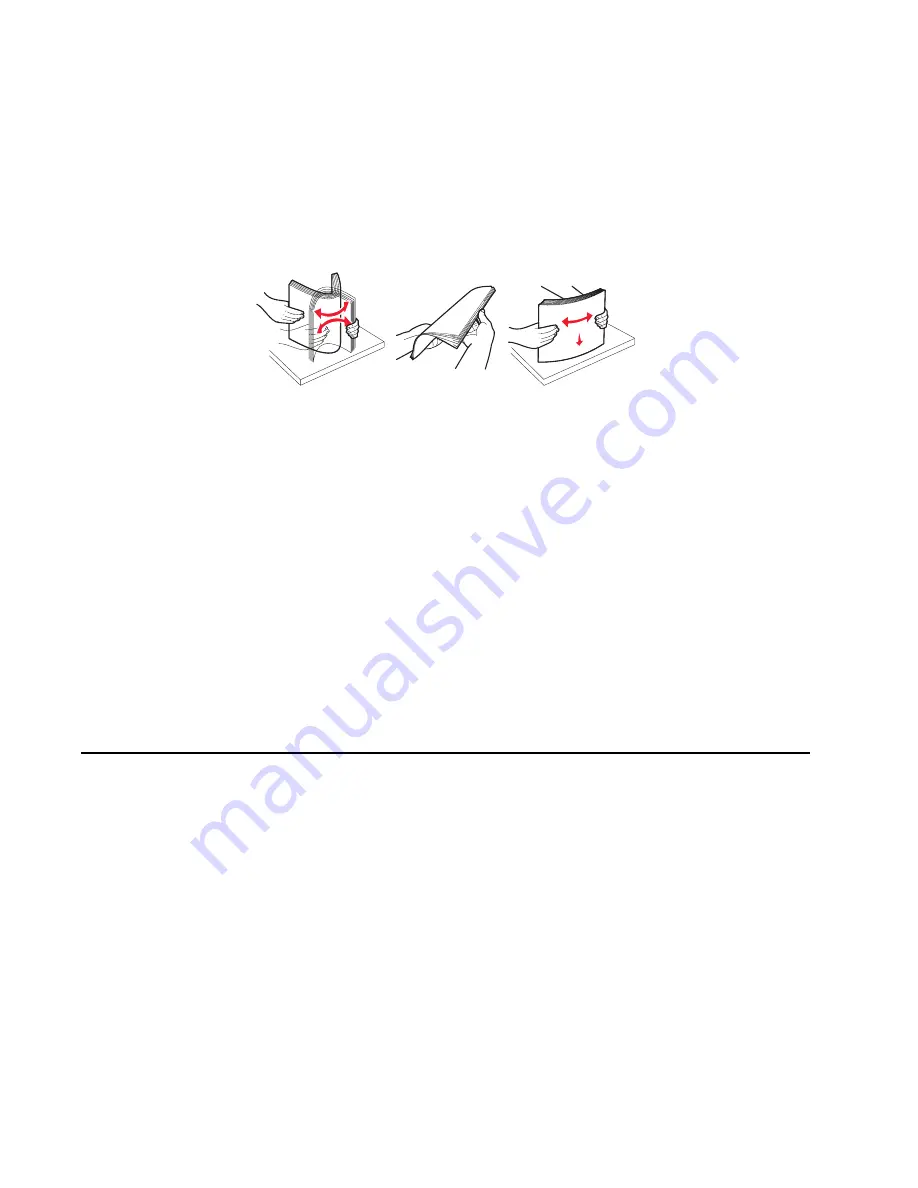
Flex, fan, and straighten print media before loading it. If jams do occur with the print media, then try feeding
one sheet at a time through the manual feeder.
•
Do not mix print media sizes, weights, or types in the same print media source.
•
Push all trays in firmly after loading them.
Note:
Make sure the media stack is below the maximum media fill indicators on the 250-sheet tray before
pushing the tray into the printer.
•
Make sure paper guides are positioned before loading the paper or specialty media.
•
Do not remove trays while a job is printing.
•
Before loading transparencies, fan the stack to prevent sheets from sticking together.
•
Do not use envelopes that:
–
Have excessive curl
–
Are stuck together
–
Are damaged in any way
–
Contain windows, holes, perforations, cutouts, or embossments
–
Have metal clasps, string ties, or metal folding bars
–
Have postage stamps attached
–
Have any exposed adhesive when the flap is in the sealed position
printing environment.
Tools
The removal and adjustment procedures require the following tools and equipment:
•
Spring hook
•
Needle nose pliers
•
Volt-ohmmeter
•
#1 and #2 Phillips screwdriver
•
Slotted screwdriver
1-8
•
Use only recommended media. Refer to the
Card Stock & Label Guide
available on the Dell Web site
at
www.dell.com
for more information about which media provides optimum results for the current
Summary of Contents for Inspiron One 2330
Page 1: ...Dell 2330d dn Service Manual 11 Dec 2008 ...
Page 6: ...vi ...
Page 11: ...Notices and safety information xi ...
Page 12: ...xii ...
Page 26: ...1 10 ...
Page 96: ...6 Remove the screw D from the gear E 7 Remove the plastic bushing F 4 14 ...
Page 103: ...Repair information 4 21 5 Disconnect the AC cable C 6 Disconnect the thermistor cable D C B D ...
Page 117: ...Repair information 4 35 5 Remove the three screws B from the left door mount B ...
Page 120: ...8 Use a screwdriver to pop the inner shaft lock B loose 9 Remove the inner shaft lock C 4 38 ...
Page 123: ...Repair information 4 41 5 Remove the e clip B 6 Remove the media feed clutch with cable C ...
Page 129: ...Repair information 4 47 7 Open the front access door and remove the lower paper guide ...
Page 137: ...Repair information 4 55 4 Tilt the rear cover and remove ...
Page 150: ...Controller board connector pin values 5 2 ...
Page 154: ...6 2 ...
Page 156: ...Assembly 1 Covers 4 3 1 5 2 9 10 6 7 8 11 12 13 7 2 ...
Page 158: ...Assembly 2 Electronics 5 2 6 3 4 10 11 12 7 13 8 9 1 7 4 ...
Page 160: ...Assembly 3 Frame 7 1 2 5 6 7 12 8 See instruction sheet in the FRU 9 10 11 3 4 3 7 6 ...
Page 164: ...7 10 ...


