


Repair information
4-37
Media ACM ASM feeder removal
1.
Remove the left side cover. See
“Left side cover removal” on page 4-23
.
2.
Remove the LVPS/HVPS. See
“LVPS/HVPS removal” on page 4-27
.
3.
Remove the duplex. See
“Duplex removal” on page 4-11
.
4.
Remove the main motor gear drive. See
“Main motor gear drive removal” on page 4-30
.
5.
Remove the media feed clutch. See
“Media feed clutch with cable removal” on page 4-40
.
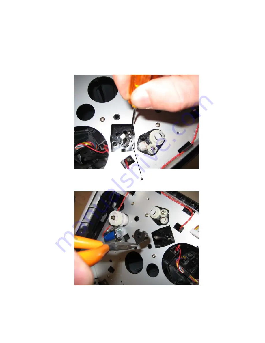
6.
Use a screwdriver to pop the shaft retainer tab (A) loose from the ACM feed shaft.
7.
Use a small pair of pliers to remove the shaft retainer tab.
Summary of Contents for Inspiron One 2330
Page 1: ...Dell 2330d dn Service Manual 11 Dec 2008 ...
Page 6: ...vi ...
Page 11: ...Notices and safety information xi ...
Page 12: ...xii ...
Page 26: ...1 10 ...
Page 96: ...6 Remove the screw D from the gear E 7 Remove the plastic bushing F 4 14 ...
Page 103: ...Repair information 4 21 5 Disconnect the AC cable C 6 Disconnect the thermistor cable D C B D ...
Page 117: ...Repair information 4 35 5 Remove the three screws B from the left door mount B ...
Page 120: ...8 Use a screwdriver to pop the inner shaft lock B loose 9 Remove the inner shaft lock C 4 38 ...
Page 123: ...Repair information 4 41 5 Remove the e clip B 6 Remove the media feed clutch with cable C ...
Page 129: ...Repair information 4 47 7 Open the front access door and remove the lower paper guide ...
Page 137: ...Repair information 4 55 4 Tilt the rear cover and remove ...
Page 150: ...Controller board connector pin values 5 2 ...
Page 154: ...6 2 ...
Page 156: ...Assembly 1 Covers 4 3 1 5 2 9 10 6 7 8 11 12 13 7 2 ...
Page 158: ...Assembly 2 Electronics 5 2 6 3 4 10 11 12 7 13 8 9 1 7 4 ...
Page 160: ...Assembly 3 Frame 7 1 2 5 6 7 12 8 See instruction sheet in the FRU 9 10 11 3 4 3 7 6 ...
Page 164: ...7 10 ...


