background image

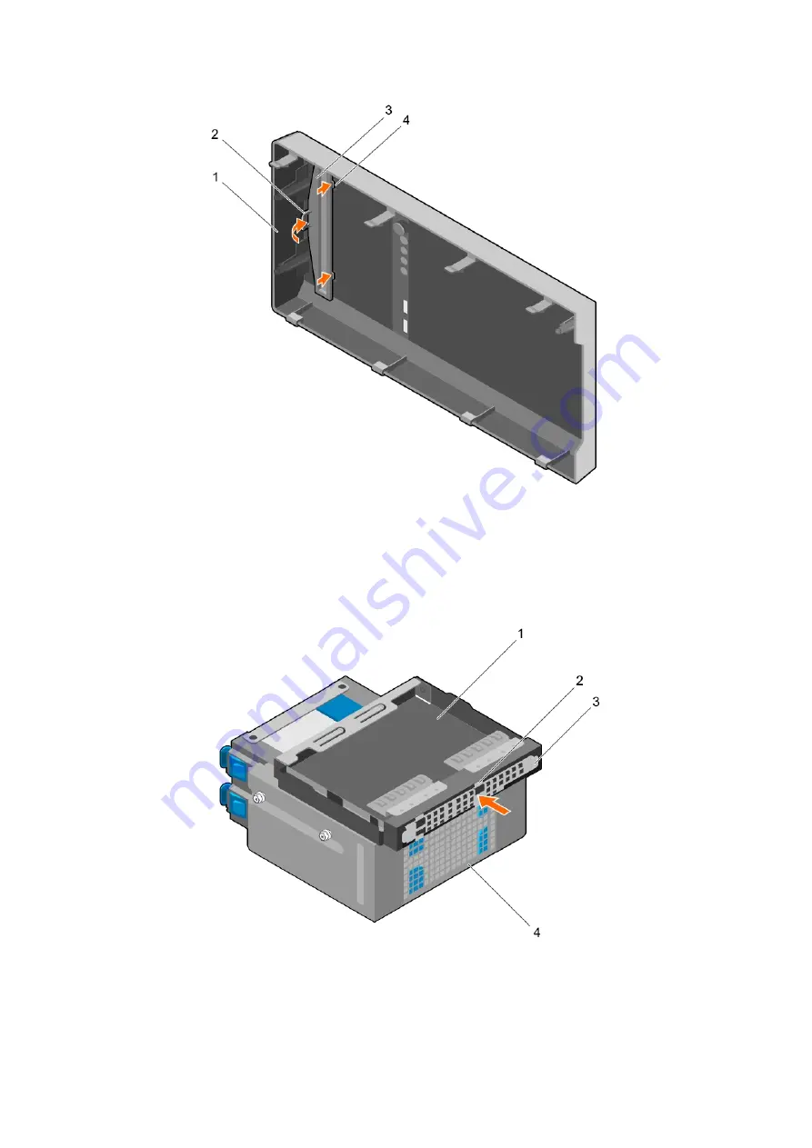
Figure 29. Installing the optical drive blank in the bezel

1. bezel

2. retention clip

3. optical drive blank

4. optical drive blank locking tab (2)

2. On the hard drive cage, hold the tabs on the optical drive filler and insert the optical drive filler into the slot on the hard drive cage.

Figure 30. Installing the optical drive filler

1. optical drive bay

2. tabs (4)

3. optical drive filler

4. hard drive cage

66

Installing and removing system components

Summary of Contents for E36S Series

Page 1: ...Dell PowerEdge T130 Owner s Manual 1 Regulatory Model E36S Series Regulatory Type E36S001 July 2020 Rev A06 ...

Page 2: ......

Page 3: ... 3 Technical specifications 19 Chassis dimensions 19 Chassis weight 20 Processor specifications 20 Expansion bus specifications 20 Memory specifications 20 Power specifications 21 Storage controller specifications 21 Drive specifications 21 Hard drives 21 Optical drive 21 Ports and connectors specifications 21 USB ports 21 NIC ports 22 iDRAC8 22 Serial connector 22 VGA ports 22 SD vFlash 22 Video ...

Page 4: ...ut Dell Lifecycle Controller 39 Changing the boot order 39 Choosing the system boot mode 39 Creating a system or setup password 39 Using your system password to secure your system 40 Deleting or changing system and setup password 40 Operating with a setup password enabled 41 Embedded systems management 41 iDRAC Settings utility 41 Entering the iDRAC Settings utility 41 Changing the thermal setting...

Page 5: ...e 68 System memory 69 General memory module installation guidelines 70 Sample memory configurations 70 Removing memory modules 72 Installing memory modules 73 Cooling fan 74 Removing the cooling fan 74 Installing the cooling fan 75 Internal USB memory key optional 76 Replacing the optional internal USB memory key 76 Expansion cards 77 Expansion card installation guidelines 77 Removing an expansion...

Page 6: ...tem 107 Troubleshooting system startup failure 107 Troubleshooting external connections 107 Troubleshooting the video subsystem 108 Troubleshooting a USB device 108 Troubleshooting a serial input and output device 108 Troubleshooting a NIC 109 Troubleshooting a wet system 109 Troubleshooting a damaged system 110 Troubleshooting the system battery 111 Troubleshooting power supply units 111 Troubles...

Page 7: ...Contacting Dell EMC 119 Accessing system information by using QRL 119 Contents 7 ...

Page 8: ...3 1200 v5 or v6 series Intel Core i3 6100 series Intel Celeron G3900 series Intel Celeron G3930 Intel Pentium G4500 series Intel Pentium G4600 series Memory modules Up to four DIMMS Hard drives Up to four 3 5 inch cabled hard drives Topics Supported configurations on PowerEdge T130 systems Front panel Back panel features Diagnostic indicators Locating service tag of your system Documentation matri...

Page 9: ...Supported configurations on PowerEdge T130 systems Figure 1 Supported configurations on PowerEdge T130 systems About the Dell PowerEdge T130 system 9 ...

Page 10: ...ndicator button or connector Icon Description 1 Diagnostic indicators Enables you to view error status during system startup The diagnostic indicators are located on the system front panel For more information see Diagnostic indicators on the front panel on page 12 2 Power on indicator power button Enables you to know the power status of the system The power on indicator glows when the system powe...

Page 11: ...USB 2 0 compliant Back panel features The back panel provides access to the features available on the back of the server such as the system identification button power supply sockets cable management arm connectors iDRAC storage media NIC ports and USB and VGA ports A majority of the expansion card ports can be accessed from the back panel The hot swappable power supply units and if installed the ...

Page 12: ...s you to install one 290 W non redundant AC PSU 7 Self diagnostic button Enables you to check the health status of the PSU 8 AC power supply status indicator Enables you to check the power supply to the PSU 9 Serial connector Enables you to connect a serial device to the system 10 Cooling fan The system cooling fan 11 VFlash Enables you to connect the vFlash card optional 12 Ethernet connector 1 E...

Page 13: ...If it is due to a problem with the PSU check the LED on the PSU Reseat the PSU If the problem persists see the Getting help section Temperature indicator The indicator flashes amber if the system experiences a thermal error for example the ambient temperature is out of range or fan failure Ensure that none of the following conditions exist A cooling fan has been removed or has failed System cover ...

Page 14: ...slowly Drive rebuilding Steady green Drive online Flashes green for three seconds amber for three seconds and then turns off after six seconds Rebuild stopped NIC indicator codes The NIC on the back panel has an indicator that provides information about the network activity and link status The activity LED indicates whether the NIC is currently connected or not The link LED indicates the speed of ...

Page 15: ...e front of the system by pulling out the information tag Alternatively the information may be on a sticker on the chassis of the system This information is used by Dell to route support calls to the appropriate personnel Documentation matrix The documentation matrix provides information on documents that you can refer to for setting up and managing your system Table 6 Documentation matrix To See t...

Page 16: ...rvices Dell Lifecycle Controller Remote Services Quick Start Guide at www dell com idracmanuals Set up use and troubleshoot OpenManage Server Administrator Dell OpenManage Server Administrator User s Guide at www dell com openmanagemanuals OpenManage Server Administrator Install use and troubleshoot OpenManage Essentials Dell OpenManage Essentials User s Guide at www dell com openmanagemanuals Ope...

Page 17: ...mation about setting up your system see the Getting Started Guide document that is shipped with your system www dell com poweredgemanuals Configuring your system For information about the iDRAC features configuring and logging in to iDRAC and managing your system remotely see the Integrated Dell Remote Access Controller User s Guide For information about understanding Remote Access Controller Admi...

Page 18: ...roubleshooting Dell OpenManage Enterprise see the Dell OpenManage Enterprise User s Guide www dell com openmanagemanuals OpenManage Enterprise For information about installing and using Dell SupportAssist see the Dell EMC SupportAssist Enterprise User s Guide https www dell com serviceabilitytools For information about partner programs enterprise systems management see the OpenManage Connections E...

Page 19: ... specifications Memory specifications Power specifications Storage controller specifications Drive specifications Ports and connectors specifications Video specifications Environmental specifications Chassis dimensions Figure 7 Chassis dimensions of the PowerEdge T130 system 3 Technical specifications 19 ...

Page 20: ...CI Express expansion slots Specification Slot 1 One full height half length x4 PCIe Gen3 card slot connected to processor Slot 2 One full height half length x8 PCIe Gen3 card slot connected to processor Slot 3 One full height full length x1 PCIe Gen3 card slot connected to Platform Controller Hub PCH Slot 4 One full height full length x4 PCIe Gen3 card slot connected to PCH Memory specifications M...

Page 21: ...on software RAID see the Dell PowerEdge RAID Controller PERC documentation at Dell com storagecontrollermanuals NOTE The upgrade from embedded controller or Software RAID controller to Hardware RAID controller is not supported Drive specifications Hard drives The PowerEdge T130 system supports SAS SATA and Nearline SAS hard drives Drives Specification Four hard drive system Up to four 3 5 inch int...

Page 22: ...raphic Array VGA port enables you to connect the system to a VGA display The PowerEdge T130 system supports one 15 pin VGA port on the back panel SD vFlash The PowerEdge T130 system supports one optional SD vFlash memory card on the iDRAC Enterprise port card NOTE The card slot is available for use only if the iDRAC8 Enterprise license is installed on your system Video specifications The PowerEdge...

Page 23: ...tions Operating 30482000 m 10 0006560 ft Storage 12 000 m 39 370 ft Operating temperature de rating Specifications Up to 35 C 95 F Maximum temperature is reduced by 1 C 300 m 33 8 F 984 25 ft above 950 m 3 117 ft The following section defines the limits to help avoid IT equipment damage and or failure from particulates and gaseous contamination If the levels of particulates or gaseous pollution ar...

Page 24: ...iquescent point less than 60 relative humidity NOTE Applies to data center and non data center environments Gaseous contamination Specifications Copper coupon corrosion rate 300 Å month per Class G1 as defined by ANSI ISA71 04 1985 Silver coupon corrosion rate 200 Å month as defined by AHSRAE TC9 9 NOTE Maximum corrosive contaminant levels measured at 50 relative humidity 24 Technical specificatio...

Page 25: ...or physical access to the system Options to set up iDRAC IP address You must configure the initial network settings based on your network infrastructure to enable the communication to and from iDRAC You can set up the IP address by using one of the following interfaces Interfaces Document Section iDRAC Settings utility See Dell Integrated Dell Remote Access Controller User s Guide at Dell com idra...

Page 26: ...l PowerEdge systems www dell com ossupport Installation and How to videos for supported operating systems on Dell PowerEdge systems https www youtube com playlist list PLe5xhhyFjDPfTCaDRFflB_VsoLpL8x84G Methods to download firmware and drivers You can download the firmware and drivers by using any of the following methods Table 13 Firmware and drivers Methods Location From the Dell Support site Gl...

Page 27: ...If you do not have the Service Tag select Detect My Product to allow the system to automatically detect your Service Tag or in General support navigate to your product 3 Click Drivers Downloads The drivers that are applicable to your selection are displayed 4 Download the drivers to a USB drive CD or DVD Initial system setup and configuration 27 ...

Page 28: ...he previous field Down arrow Moves to the next field Enter Enables you to type a value in the selected field if applicable or follow the link in the field Spacebar Expands or collapses a drop down list if applicable Tab Moves to the next focus area NOTE This feature is applicable for the standard graphic browser only Esc Moves to the previous page until you view the main screen Pressing Esc in the...

Page 29: ...ription System Information Specifies information about the system such as the system model name BIOS version and Service Tag Memory Settings Specifies information and options related to the installed memory Processor Settings Specifies information and options related to the processor such as speed and cache size SATA Settings Specifies options to enable or disable the integrated SATA controller an...

Page 30: ...mplex programmable logic device CPLD firmware UEFI Compliance Version Specifies the UEFI compliance level of the system firmware Memory Settings details About this task The Memory Settings screen details are explained as follows Option Description System Memory Size Specifies the memory size in the system System Memory Type Specifies the type of memory installed in the system System Memory Speed S...

Page 31: ...Cache Unit DCU IP prefetcher This option is set to Enabled by default Configurable TDP Enables you to reconfigure the processor Thermal Design Power TDP levels during POST based on the power and thermal delivery capabilities of the system TDP verifies the maximum heat the cooling system is needed to dissipate This option is set to Nominal by default NOTE This option is only available on certain st...

Page 32: ...SATA port Capacity Specifies the total capacity of the hard drive This field is undefined for removable media devices such as optical drives Port C For AHCI or RAID mode BIOS support is always enabled Option Description Model Specifies the drive model of the selected device Drive Type Specifies the type of drive attached to the SATA port Capacity Specifies the total capacity of the hard drive This...

Page 33: ... are attempted to boot in the order selected in the Hard Disk Drive Sequence This option is not enabled for UEFI Boot Mode Boot Option Settings Configures the boot sequence and the boot devices BIOS Boot Settings Enables or disables BIOS boot options NOTE This option is enabled only if the boot mode is BIOS UEFI Boot Settings Enables or disables UEFI Boot options The Boot options include IPv4 PXE ...

Page 34: ...tem I O Snoop Holdoff Response Selects the number of cycles PCI I O can withhold snoop requests from the CPU to allow time to complete its own write to LLC This setting can help improve performance on workloads where throughput and latency are critical Embedded Video Controller Enables or disables the Embedded Video Controller option This option is set to Enabled by default Current State of Embedd...

Page 35: ... rate for console redirection The BIOS attempts to determine the baud rate automatically This failsafe baud rate is used only if the attempt fails and the value must not be changed This option is set to 115200 by default Remote Terminal Type Sets the remote console terminal type This option is set to VT 100 VT 220 by default Redirection After Boot Enables or disables the BIOS console redirection w...

Page 36: ... the system password This option is set to Enabled by default and is read only if the password jumper is not installed in the system Setup Password Sets the setup password This option is read only if the password jumper is not installed in the system Password Status Locks the system password This option is set to Unlocked by default TPM Security NOTE The TPM menu is available only when the TPM mod...

Page 37: ...et to Custom About this task To view the Secure Boot Custom Policy Settings screen click System Setup Main Menu System BIOS System Security Secure Boot Custom Policy Settings The Secure Boot Custom Policy Settings screen details are explained as follows Option Description Platform Key Imports exports deletes or restores the platform key PK Key Exchange Key Database Enables you to import export del...

Page 38: ...hat ISC results can be applied It takes the system longer to be ready due to the forced system reset When disabled ISC does not execute About Boot Manager Boot manager enables you to add delete and arrange boot options You can also access System Setup and boot options without restarting the system Viewing Boot Manager To enter Boot Manager Steps 1 Turn on or restart your system 2 Press F11 when yo...

Page 39: ...u want the system to boot into CAUTION Switching the boot mode may prevent the system from booting if the operating system is not installed in the same boot mode 3 After the system boots in the specified boot mode proceed to install your operating system from that mode NOTE Operating systems must be UEFI compatible to be installed from the UEFI boot mode DOS and 32 bit operating systems do not sup...

Page 40: ...rompts you to reenter your password You have three attempts to type the correct password After the third unsuccessful attempt the system displays an error message that the system has stopped functioning and must be turned off Even after you turn off and restart the system the error message is displayed until the correct password is entered Deleting or changing system and setup password Prerequisit...

Page 41: ...Lifecycle Controller For more information about setting up the Dell Lifecycle Controller configuring hardware and firmware and deploying the operating system see the Dell Lifecycle Controller documentation at Dell com idracmanuals iDRAC Settings utility The iDRAC settings utility is an interface to set up and configure the iDRAC parameters by using UEFI You can enable or disable various iDRAC para...

Page 42: ...tem is powered on may expose you to a risk of electric shock CAUTION Do not operate the system without the cover for a duration exceeding five minutes CAUTION Many repairs may only be done by a certified service technician You should only perform troubleshooting and simple repairs as authorized in your product documentation or as directed by the online or telephone service and support team Damage ...

Page 43: ...peripherals Related tasks Installing the system cover on page 44 Recommended tools You need the following tools to perform the installation and removal procedures Phillips 2 screwdriver Plastic scribe Wrist grounding strap connected to ground System cover The system cover protects the components inside the system and helps in maintaining air flow inside the system Removing the system cover activat...

Page 44: ... the system cover on page 44 Installing the system cover Prerequisites 1 Ensure that you follow the Safety instructions on page 42 2 Follow the procedure listed in Before working inside your system on page 43 3 Ensure that all internal cables are connected and placed out of the way and that no tools or extra parts are left inside the system Steps 1 Align the tabs on the system cover with the corre...

Page 45: ... attached to the front side of the server and prevents accidents while removing the hard drive or when pressing the reset or power button The front bezel can also be locked for additional security Removing the bezel Prerequisites 1 Ensure that you follow the Safety instructions on page 42 2 Follow the procedure listed in Before working inside your system on page 43 Steps 1 Lift the retention clips...

Page 46: ...ng the bezel on page 46 Installing the bezel Prerequisites 1 Ensure that you follow the Safety instructions on page 42 2 Follow the procedure listed in Before working inside your system on page 43 Steps 1 Insert the bezel tabs into the bezel tab slots on the chassis 2 Press the bezel into the chassis until the retention clips lock into place 46 Installing and removing system components ...

Page 47: ...Figure 11 Installing the bezel a retention clips 4 b bezel Next steps 1 Follow the procedure listed in After working inside your system on page 43 Installing and removing system components 47 ...

Page 48: ...vice technician You should only perform troubleshooting and simple repairs as authorized in your product documentation or as directed by the online or telephone service and support team Damage due to servicing that is not authorized by Dell is not covered by your warranty Read and follow the safety instructions that are shipped with your product 1 Ensure that you follow the Safety instructions on ...

Page 49: ...talling the intrusion switch Prerequisites CAUTION Many repairs may only be done by a certified service technician You should only perform troubleshooting and simple repairs as authorized in your product documentation or as directed by the online or telephone service and support team Damage due to servicing that is not authorized by Dell is not covered by your warranty Read and follow the safety i...

Page 50: ... Prerequisites CAUTION Many repairs may only be done by a certified service technician You should only perform troubleshooting and simple repairs as authorized in your product documentation or as directed by the online or telephone service and support team Damage due to servicing that is not authorized by Dell is not covered by your warranty Read and follow the safety instructions that are shipped...

Page 51: ...system Figure 15 Removing the control panel assembly 1 screw 3 2 control panel assembly 3 control panel assembly guide 2 4 control panel assembly guide slot 2 Next steps 1 Install the control panel assembly 2 Install the bezel 3 Follow the procedure listed in After working inside your system on page 43 Related tasks Removing the bezel on page 45 Installing the control panel assembly on page 52 Ins...

Page 52: ...y instructions on page 42 2 Follow the procedure listed in Before working inside your system on page 43 3 Remove the bezel 4 Keep the Phillips 2 screwdriver ready Steps 1 Insert the control panel assembly into the guide slot and slide it downward to lock the assembly into place 2 To secure the control panel insert and tighten the screws to the chassis 3 Route the control panel and USB data cables ...

Page 53: ...or more information about these hard drives see the 512e and 4Kn Disk Formats white paper and 4K Sector HDD FAQ document at Dell com poweredgemanuals All hard drives are connected to the system board through the hard drive backplane Hard drives are supplied in hot swappable hard drive carriers that fit in the hard drive slots When you format a hard drive allow enough time for the formatting to be ...

Page 54: ...he bezel on page 46 Installing the hard drive cage Prerequisites 1 Ensure that you follow the Safety instructions on page 42 2 Follow the procedure listed in Before working inside your system on page 43 3 Disconnect all peripherals connected to the control panel assembly 4 Remove the bezel CAUTION Many repairs may only be done by a certified service technician You should only perform troubleshooti...

Page 55: ...n page 46 Removing a hard drive carrier from the hard drive cage Prerequisites CAUTION Many repairs may only be done by a certified service technician You should only perform troubleshooting and simple repairs as authorized in your product documentation or as directed by the online or telephone service and support team Damage due to servicing that is not authorized by Dell is not covered by your w...

Page 56: ...cage 4 Install the bezel 5 Reconnect the peripherals disconnected from the control panel assembly 6 Follow the procedure listed in After working inside your system on page 43 Related tasks Removing the bezel on page 45 Removing the hard drive cage on page 53 Installing a hard drive carrier into the hard drive cage on page 56 Installing the hard drive cage on page 54 Installing the bezel on page 46...

Page 57: ... Insert the hard drive carrier into the hard drive cage until it clicks into place Figure 20 Installing a hard drive carrier into the hard drive cage 1 hard drive carrier 2 hard drive 3 retention clips 2 4 hard drive cage Next steps 1 Install the hard drive cage 2 Reconnect the power and data cables to the hard drives and optical drive in the hard drive cage 3 Install the bezel 4 Reconnect the per...

Page 58: ...ted in Before working inside your system on page 43 3 If connected disconnect the power and data cables from the hard drive in the hard drive bay Steps Press the retention clips inward and lift the hard drive carrier from the hard drive bay Figure 21 Removing a hard drive carrier from the hard drive bay a hard drive b retention clips on hard drive carrier 2 c hard drive power and data cables 2 Nex...

Page 59: ...ide your system on page 43 Steps Insert the hard drive carrier into the hard drive bay until it clicks into place Figure 22 Installing a hard drive carrier into the hard drive bay a hard drive b retention clips on hard drive carrier 2 c hard drive power and data cables 2 Next steps 1 If disconnected connect the power and data cables to the hard drive in the hard drive bay 2 Follow the procedure li...

Page 60: ...ay on page 58 Removing a hard drive carrier from the hard drive cage on page 55 Installing a hard drive into a hard drive carrier on page 60 Installing a hard drive into a hard drive carrier Prerequisites CAUTION Many repairs may only be done by a certified service technician You should only perform troubleshooting and simple repairs as authorized in your product documentation or as directed by th...

Page 61: ...alling a hard drive into a hard drive carrier a pins 4 b hard drive carrier c hard drive Next steps 1 Depending on your requirement install the hard drive carrier in the hard drive cage or the hard drive bay 2 Follow the procedure listed in After working inside your system on page 43 Installing and removing system components 61 ...

Page 62: ...he four 3 5 inch SATA hard drives from the PERC card 1 system board 2 SATA connector on system board 3 SATA connector on optical drive 4 optical drive 5 hard drive 6 SATA connector on hard drive 7 SAS A connector on PERC card 8 PERC card 62 Installing and removing system components ...

Page 63: ...recommends that 4 TB hard drives be used only in systems configured with a PERC controller CAUTION Using 4 TB hard drives in the system without a PERC controller might cause hard drive 1 to overheat under excessive work load leading to a potential failure of the hard drive About this task When 4 TB hard drives are used in a system without a PERC controller the speed of the cooling fan needs to be ...

Page 64: ...our system on page 43 3 Disconnect all peripherals connected to the control panel assembly 4 Remove the bezel 5 If connected disconnect the power and data cable from the optical drive and hard drives 6 Remove the hard drive cage Steps 1 On the bezel press down on the retention clip of the optical drive blank and pull the blank out of the bezel Figure 27 Removing the optical drive blank from the be...

Page 65: ...bezel on page 46 Installing the optical drive blank and filler The optical drive blank is on the bezel and the optical drive filler is located in the optical drive slot on the hard drive cage Prerequisites 1 Ensure that you follow the Safety instructions on page 42 2 Follow the procedure listed in Before working inside your system on page 43 3 Disconnect all peripherals connected to the control pa...

Page 66: ... blank locking tab 2 2 On the hard drive cage hold the tabs on the optical drive filler and insert the optical drive filler into the slot on the hard drive cage Figure 30 Installing the optical drive filler 1 optical drive bay 2 tabs 4 3 optical drive filler 4 hard drive cage 66 Installing and removing system components ...

Page 67: ...vicing that is not authorized by Dell is not covered by your warranty Read and follow the safety instructions that are shipped with your product 1 Ensure that you follow the Safety instructions on page 42 2 Follow the procedure listed in Before working inside your system on page 43 3 Disconnect all peripherals connected to the I O module 4 Remove the bezel 5 If connected disconnect the power and d...

Page 68: ...rected by the online or telephone service and support team Damage due to servicing that is not authorized by Dell is not covered by your warranty Read and follow the safety instructions that are shipped with your product 1 Ensure that you follow the Safety instructions on page 42 2 Follow the procedure listed in Before working inside your system on page 43 3 Disconnect all peripherals connected to...

Page 69: ...cal drive on page 68 Installing the hard drive cage on page 54 Installing the bezel on page 46 System memory Your system supports DDR4 ECC unbuffered DIMMs UDIMMs NOTE MT s indicates memory module speed in Mega Transfers per second Memory bus operating frequency can be 1600 MT s 1866 MT s 2133 MT s or 2400 MT s depending on the following factors System profile selected for example Performance Opti...

Page 70: ...based DIMMs can be mixed Up to two dual or single rank ECC UDIMMs can be populated per channel Populate DIMM sockets only if a processor is installed For single processor systems sockets A1 to A4 are available Populate all sockets with white release levers first and then all the sockets with black release levers When mixing memory modules with different capacities populate the sockets with memory ...

Page 71: ... 2400 MT s 2R x8 2400 MT s A1 A2 8 1 1R x8 2400 MT s 1R x8 2133 MT s 2R x8 2133 MT s 1R x8 1866 MT s 2R x8 1866 MT s A1 16 4 4 1R x8 2400 MT s 2R x8 2400 MT s A1 A2 A3 A4 8 2 1R x8 2400 MT s 1R x8 2133 MT s 2R x8 2133 MT s A1 A2 16 1 2R x8 2400 MT s 1R x8 1866 MT s 2R x8 1866 MT s A1 32 8 4 1R x8 2400 MT s 2R x8 2400 MT s A1 A2 A3 A4 16 2 2R x8 2400 MT s 1R x8 2133 MT s 2R x8 2133 MT s 1R x8 1866 ...

Page 72: ...n powered down Allow the memory modules to cool before handling them Handle the memory modules by the card edges and avoid touching the components or metallic contacts on the memory module Steps 1 Locate the appropriate memory module socket CAUTION Handle each memory module only by the card edges ensuring not to touch the middle of the memory module or metallic contacts 2 To release the memory mod...

Page 73: ...metallic contacts on the memory module Steps 1 Locate the appropriate memory module socket CAUTION Handle each memory module only by the card edges ensuring not to touch the middle of the memory module or metallic contacts CAUTION To prevent damage to the memory module or the memory module socket during installation do not bend or flex the memory module insert both ends of the memory module simult...

Page 74: ...tation or as directed by the online or telephone service and support team Damage due to servicing that is not authorized by Dell is not covered by your warranty Read and follow the safety instructions that are shipped with your product CAUTION Do not remove or install the cooling fan by holding the blades CAUTION Never operate your system with the system fan removed System can overheat and result ...

Page 75: ...your product documentation or as directed by the online or telephone service and support team Damage due to servicing that is not authorized by Dell is not covered by your warranty Read and follow the safety instructions that are shipped with your product CAUTION Do not remove or install the system fan by holding the blades 1 Ensure that you follow the Safety instructions on page 42 2 Follow the p...

Page 76: ... be enabled by the Internal USB Port option in the Integrated Devices screen of System Setup To boot from the USB memory key configure the USB memory key with a boot image and then specify the USB memory key in the boot sequence in System Setup NOTE To locate the internal USB connector INT_USB on the system board see System board jumpers and connectors on page 104 Replacing the optional internal U...

Page 77: ...SB memory key a USB memory key b USB port Figure 39 Installing the internal USB memory key a USB memory key b USB port Next steps 1 Follow the procedure listed in the After working inside your system section 2 While booting press F2 to enter System Setup and verify that the USB memory key is detected by the system Expansion cards NOTE An SEL event is logged if an expansion card is unsupported or m...

Page 78: ...uisites CAUTION Many repairs may only be done by a certified service technician You should only perform troubleshooting and simple repairs as authorized in your product documentation or as directed by the online or telephone service and support team Damage due to servicing that is not authorized by Dell is not covered by your warranty Read and follow the safety instructions that are shipped with y...

Page 79: ...support team Damage due to servicing that is not authorized by Dell is not covered by your warranty Read and follow the safety instructions that are shipped with your product 1 Ensure that you follow the Safety instructions on page 42 2 Follow the procedure listed in Before working inside your system Steps 1 Unpack the expansion card and prepare it for installation For instructions see the documen...

Page 80: ...sion card blank Next steps Follow the procedure listed in After working inside your system SD vFlash card optional An SD vFlash card is a Secure Digital SD card that plugs into the SD vFlash card slot in the iDRAC port card It provides persistent on demand local storage and a custom deployment environment that enables automation of server configuration scripts and imaging It emulates USB device s ...

Page 81: ...is used for advanced management of the system An SD vFlash card is a Secure Digital SD card that plugs into the SD vFlash card slot in the system It provides persistent on demand local storage and a custom deployment environment that allows automation of server configuration scripts and imaging It emulates USB device s For more information see the Integrated Dell Remote Access Controller User s Gu...

Page 82: ...the safety instructions that are shipped with your product 1 Follow the safety guidelines listed in the Safety instructions section 2 Follow the procedure listed in the Before working inside your system section 3 Keep the Phillips 2 screwdriver ready 4 If connected disconnect the network cable from the iDRAC port card Steps 1 Loosen the screw securing the iDRAC port card holder to the system board...

Page 83: ...mage due to servicing that is not authorized by Dell is not covered by your warranty Read and follow the safety instructions that are shipped with your product 1 Ensure that you follow the safety guidelines listed in the Safety instructions section 2 Follow the procedure listed in the Before working inside your system section 3 Keep the Phillips 2 screwdriver ready Steps 1 Align and insert the tab...

Page 84: ...from a processor unless you intend to remove the processor The heat sink is necessary to maintain proper thermal conditions NOTE This is a Field Replaceable Unit FRU Removal and installation procedures should be performed only by Dell certified service technicians 1 Ensure that you follow the safety guidelines listed in the Safety instructions section 2 Keep the Phillips 2 screwdriver ready 3 Foll...

Page 85: ...85 Removing the processor Prerequisites CAUTION Many repairs may only be done by a certified service technician You should only perform troubleshooting and simple repairs as authorized in your product documentation or as directed by the online or telephone service and support team Damage due to servicing that is not authorized by Dell is not covered by your warranty Read and follow the safety inst...

Page 86: ...ket under strong pressure Be aware that the release lever can spring up suddenly if not firmly held Steps 1 Release the socket lever by pushing the lever down and out from under the tab on the processor shield 2 Lift the lever upward until the processor shield lifts CAUTION The processor socket pins are fragile and can be permanently damaged Be careful not to bend the pins in the processor socket ...

Page 87: ...d by the online or telephone service and support team Damage due to servicing that is not authorized by Dell is not covered by your warranty Read and follow the safety instructions that are shipped with your product NOTE This is a Field Replaceable Unit FRU Removal and installation procedures should be performed only by Dell certified service technicians 1 Ensure that you follow the Safety instruc...

Page 88: ...sor When the processor is positioned correctly it engages easily into the socket CAUTION Positioning the processor incorrectly can permanently damage the system board or the processor Be careful not to bend the pins in the socket 4 Align the pin 1 indicator of the processor with the triangle on the socket 5 Place the processor on the socket such that the slots on the processor align with the socke...

Page 89: ...ing the heat sink on page 89 Installing the heat sink Prerequisites CAUTION Many repairs may only be done by a certified service technician You should only perform troubleshooting and simple repairs as authorized in your product documentation or as directed by the online or telephone service and support team Damage due to servicing that is not authorized by Dell is not covered by your warranty Rea...

Page 90: ...grease c thermal grease syringe 3 Place the heat sink onto the processor 4 Tighten one of the four screws to secure the heat sink to the system board 5 Tighten the screw diagonally opposite to the first screw you tightened NOTE Do not overtighten the heat sink retention screws when installing the heat sink To prevent overtightening tighten the retention screw until resistance is felt The screw ten...

Page 91: ...authorized by Dell is not covered by your warranty Read and follow the safety instructions that are shipped with your product 1 Ensure that you follow the Safety instructions on page 42 2 Follow the procedure listed in Before working inside your system on page 43 3 Keep the Phillips 2 screwdriver ready Steps 1 Disconnect all the power cables from the PSU to the system board 2 Remove the screws sec...

Page 92: ...ly be done by a certified service technician You should only perform troubleshooting and simple repairs as authorized in your product documentation or as directed by the online or telephone service and support team Damage due to servicing that is not authorized by Dell is not covered by your warranty Read and follow the safety instructions that are shipped with your product 1 Ensure that you follo...

Page 93: ...nsert and tighten the screws on the back of the chassis 3 Connect the power cables to the system board connectors Figure 53 Installing the PSU 1 screws 4 2 PSU 3 release tab 4 P1 power cable 5 P2 power cable 6 PSU support guide Next steps Follow the procedure listed in After working inside your system on page 43 Installing and removing system components 93 ...

Page 94: ...or telephone service and support team Damage due to servicing that is not authorized by Dell is not covered by your warranty Read and follow the safety instructions that are shipped with your product NOTE This is a Field Replaceable Unit FRU Removal and installation procedures must be performed only by Dell certified service technicians Steps 1 Locate the battery socket For more information see th...

Page 95: ...r warranty Read and follow the safety instructions that are shipped with your product NOTE This is a Field Replaceable Unit FRU Removal and installation procedures must be performed only by Dell certified service technicians CAUTION If you are using the Trusted Program Module TPM with an encryption key you may be prompted to create a recovery key during program or System Setup Be sure to create an...

Page 96: ...em board and slide the system board toward the front of the chassis 3 Hold the system board by the touch points and lift it out of the chassis CAUTION To prevent damage to the system board do not lift the system board by holding a memory module processor or other components hold the system board by its edges only Figure 56 Removing the system board a touch point 2 b system board c system board t h...

Page 97: ...ard Prerequisites CAUTION Many repairs may only be done by a certified service technician You should only perform troubleshooting and simple repairs as authorized in your product documentation or as directed by the online or telephone service and support team Damage due to servicing that is not authorized by Dell is not covered by your warranty Read and follow the safety instructions that are ship...

Page 98: ...ts edges and orient it toward the back of the chassis 2 Lower the system board into the chassis until the connectors at the back of the system board align with the slots on the back of the chassis 3 Tighten the screws that secure the system board to the chassis Figure 58 Install the system board a touch point 2 b system board c system board t handle post Next steps 1 If required install the Truste...

Page 99: ...ort your new or existing iDRAC Enterprise license For more information see the Integrated Dell Remote Access Controller User s Guide at www dell com poweredgemanuals Trusted Platform Module Trusted Platform Module TPM is a dedicated microprocessor designed to secure hardware by integrating cryptographic keys into devices A software can use a Trusted Platform Module to authenticate hardware devices...

Page 100: ...until the rivet snaps into place Figure 59 Installing the TPM 1 rivet slot on the system board 2 plastic rivet 3 TPM 4 TPM connector Next steps 1 Install the system board 2 Follow the procedure listed in the After working inside your system section Initializing the TPM for BitLocker users Steps Initialize the TPM For more information about initializing the TPM see https technet microsoft com en us...

Page 101: ...7 Enter System Setup again 8 On the System Setup Main Menu screen click System BIOS System Security Settings 9 From the Intel TXT option select On Installing and removing system components 101 ...

Page 102: ...lowing you to Run tests automatically or in an interactive mode Repeat tests Display or save test results Run thorough tests to introduce additional test options to provide extra information about the failed device s View status messages that inform you if tests are completed successfully View error messages that inform you of problems encountered during testing When to use the Embedded System Dia...

Page 103: ...System diagnostics controls Menu Description Configuration Displays the configuration and status of all detected devices Results Displays the results of all tests that are executed System health Provides the current overview of the system performance Event log Displays a time stamped log of the results of all tests run on the system This is displayed if at least one event description is recorded U...

Page 104: ... board jumpers and connectors Figure 60 System board jumpers and connectors Table 19 System board jumpers and connectors Ite m Connector Description 1 FP_USB Front panel USB connector 2 CTRL_PNL Control panel 3 PIB_CONN PIB connector 4 BATTERY System battery 5 Slot 1 PCIE_G3_X4 CPU PCIe card connector 1 8 104 Jumpers and connectors ...

Page 105: ...tor 25 HDD ODD_PWR Hard drive power connector 26 BP_SIG Backplane signal connector System board jumper settings CAUTION Many repairs may only be done by a certified service technician You should only perform troubleshooting and simple repairs as authorized in your product documentation or as directed by the online or telephone service and support team Damage due to servicing that is not authorized...

Page 106: ...er 3 Move the jumper on the system board jumper from pins 2 and 3 to pins 1 and 2 4 Install the system cover The existing passwords are not disabled erased until the system boots with the jumper on pins 1 and 2 However before you assign a new system and or setup password you must move the jumper back to pins 2 and 3 NOTE If you assign a new system and or setup password with the jumper on pins 1 an...

Page 107: ...roubleshooting an internal USB key Troubleshooting a micro SD card Troubleshooting an optical drive Troubleshooting a drive or SSD Troubleshooting a storage controller Troubleshooting expansion cards Troubleshooting processors System messages Troubleshooting system startup failure If you boot the system to the BIOS boot mode after installing an operating system from the UEFI Boot Manager the syste...

Page 108: ...s Automatic or Standard OS Use 5 If the problem is not resolved replace the keyboard and or mouse with a known working keyboard or mouse If the problem is not resolved proceed to step 6 to troubleshoot other USB devices attached to the system If the problem is not resolved proceed to troubleshoot other USB devices attached to the system 6 Turn off all attached USB devices and disconnect them from ...

Page 109: ... or hub 4 Ensure that the appropriate drivers are installed and the protocols are bound For more information see the NIC documentation 5 Enter System Setup and confirm that the NIC ports are enabled on the Integrated Devices screen 6 Ensure that all the NICs hubs and switches on the network are set to the same data transmission speed and duplex For more information see the documentation for each n...

Page 110: ...em Prerequisites CAUTION Many repairs may only be done by a certified service technician You should only perform troubleshooting and simple repairs as authorized in your product documentation or as directed by the online or telephone service and support team Damage due to servicing that is not authorized by Dell is not covered by your warranty Read and follow the safety instructions that are shipp...

Page 111: ...displayed in System Setup are not correct check the System Error Log SEL for system battery messages Next steps If the problem persists see the Getting help section Troubleshooting power supply units Prerequisites CAUTION Many repairs may only be done by a certified service technician You should only perform troubleshooting and simple repairs as authorized in your product documentation or as direc...

Page 112: ...ple repairs as authorized in your product documentation or as directed by the online or telephone service and support team Damage due to servicing that is not authorized by Dell is not covered by your warranty Read and follow the safety instructions that are shipped with your product Ensure that the following conditions exist System cover cooling shroud EMI filler panel or back filler bracket is n...

Page 113: ... NOTE NVDIMM N battery is not hot pluggable Steps 1 If the system is operational run the appropriate diagnostic test See the Using system diagnostics section for the available diagnostic tests If the diagnostic tests indicate a fault follow the corrective actions that are provided by the diagnostic tests 2 If the system is not operational turn off the system and attached peripherals and unplug the...

Page 114: ... by the online or telephone service and support team Damage due to servicing that is not authorized by Dell is not covered by your warranty Read and follow the safety instructions that are shipped with your product Steps 1 Enter System Setup and ensure that the USB key port is enabled on the Integrated Devices screen 2 Turn off the system and attached peripherals and disconnect the system from the...

Page 115: ...ice and support team Damage due to servicing that is not authorized by Dell is not covered by your warranty Read and follow the safety instructions that are shipped with your product Steps 1 Try using a different CD or DVD 2 If the problem is not resolved enter System Setup and ensure that the integrated SATA controller and the drive s SATA port are enabled 3 Run the appropriate diagnostic test 4 ...

Page 116: ...zed by Dell is not covered by your warranty Read and follow the safety instructions that are shipped with your product NOTE When troubleshooting a controller see the documentation for your operating system and the controller NOTE Mini PERC socket is not hot pluggable 1 Run the appropriate diagnostic test See the Using system diagnostics section 2 Turn off the system and attached peripherals and di...

Page 117: ...l expansion cards installed in the system 10 Install the system cover 11 Run the appropriate diagnostic test See the Using system diagnostics section If the tests fail see the Getting help section 12 For each expansion card you removed in step 8 perform the following steps a Turn off the system and attached peripherals and disconnect the system from the electrical outlet b Remove the system cover ...

Page 118: ... or n no NOTE Warning messages are generated by either the application or the operating system For more information see the documentation that shipped with the operating system or application Diagnostic messages The system diagnostic utility generates messages if there are errors detected when you run diagnostic tests on your system For more information about system diagnostics see the For informa...

Page 119: ...nt c Select your product The support page that lists the various support categories is displayed 5 For contact details of Dell EMC Global Technical Support a Click Global Technical Support b Enter your system Service Tag in the Enter your Service Tag field on the Contac Us webpage Accessing system information by using QRL You can use the Quick Resource Locator QRL to get immediate access to the in...

Page 120: ...120 Getting help ...

Reviews: